
Air conditioner for automobile

a technology for air conditioners and automobiles, applied in the direction of domestic cooling devices, lighting and heating devices, electric propulsion mountings, etc., can solve the problems of insufficient cooling wind amount, complex shape of ducts forming air flow paths, and low heat exchange efficiency

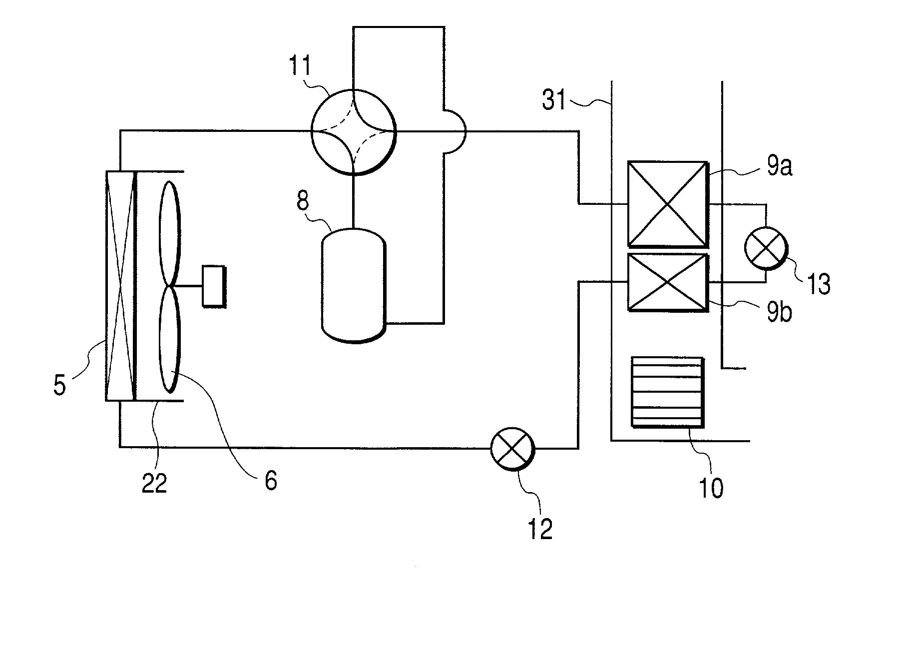
Inactive Publication Date: 2003-01-30
HITACHI LTD
View PDF0 Cites 32 Cited by
  • Summary
  • Abstract
  • Description
  • Claims
  • Application Information

AI Technical Summary

Benefits of technology

[0011] It is a second object of the invention to provide an air conditioner for an automobile removing restriction on arrangement of a driving motor and a motor driving power source and capable of achieving small-sized and light-weighted formation by promoting cooling capacity of the driving motor and the motor driving power source by a cooling fluid in heating operation.
[0012] It is a third object of the invention to provide an air conditioner for an automobile removing restriction on arrangement of electric apparatus, capable of achieving small-sized and light-weighted formation by promoting heating capacity by effectively utilizing waste heat in heating operation and promoting cooling capacity of the electric apparatus by a cooling fluid, capable of definitely defrosting an exterior heat exchanger by closing an air flow path of the exterior heat exchanger in heating operation and capable of promoting cooling function by flowing wind to a radiator and the exterior heat exchanger in parallel with each other in a cooling operation.

Problems solved by technology

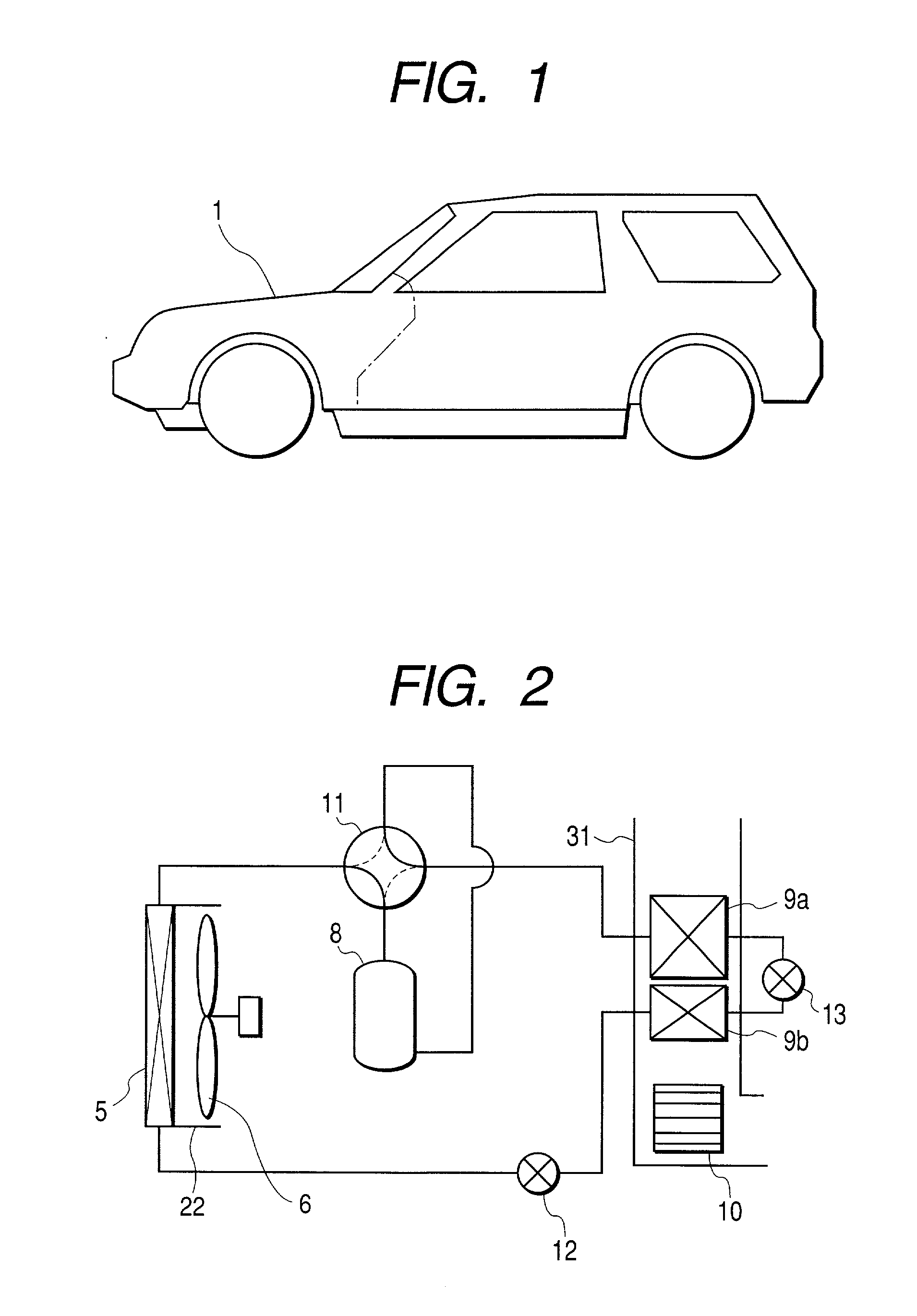
Therefore, although according to the conventional engine-driven automobile, heating can be carried out by utilizing waste heat at a high temperature, according to the electric automobile, waste heat at a high temperature by engine is not be provided normally and therefore, it is necessary to carry out heating by a heat pump using a refrigeration cycle similar to the air conditioner for household use.
Further, when frost is formed and developed at the exterior heat exchanger depending on conditions of temperature and humidity of the outside air in heating, the heating cannot be carried out and therefore, defrosting is carried out by guiding gas at a high temperature delivered from the compressor of the refrigeration cycle to the exterior heat exchanger to thereby heat the exterior heat exchanger in a state in which the first air flow path is also closed and air does not flow through the exterior heat exchanger.
When the driving motor is arranged at a side or a rear side of the exterior heat exchanger in order to improve the restriction, there poses a problem that a shape of a duct constituting the air flow path becomes complicated and expensive and a cooling wind amount can not be provided sufficiently.
Further, according to the conventional technology, heat exchange is carried out between an outer peripheral face of the driving motor and outside air and therefore, there poses a problem that the heat exchange efficiency is low and waste heat of the driving motor cannot be utilized sufficiently.
When the outer peripheral face of the driving motor is provided with fins in order to increase the heat exchange amount between the driving motor and the outside air, there poses a problem that an outer diameter of the driving motor is increased and performance of containing the driving motor is deteriorated.
Further, according to the conventional technology, there is not a description with regard to a case in which in heating by the heat pump, when snow or rain falls, snow or rain reaches the exterior heat exchanger by air flow caused by travel motion of the automobile and frost formation on the exterior heat exchanger is accelerated or the frost is frozen and heating is hampered.

Method used


Image

  • Air conditioner for automobile
  • Air conditioner for automobile
  • Air conditioner for automobile

Examples


second embodiment

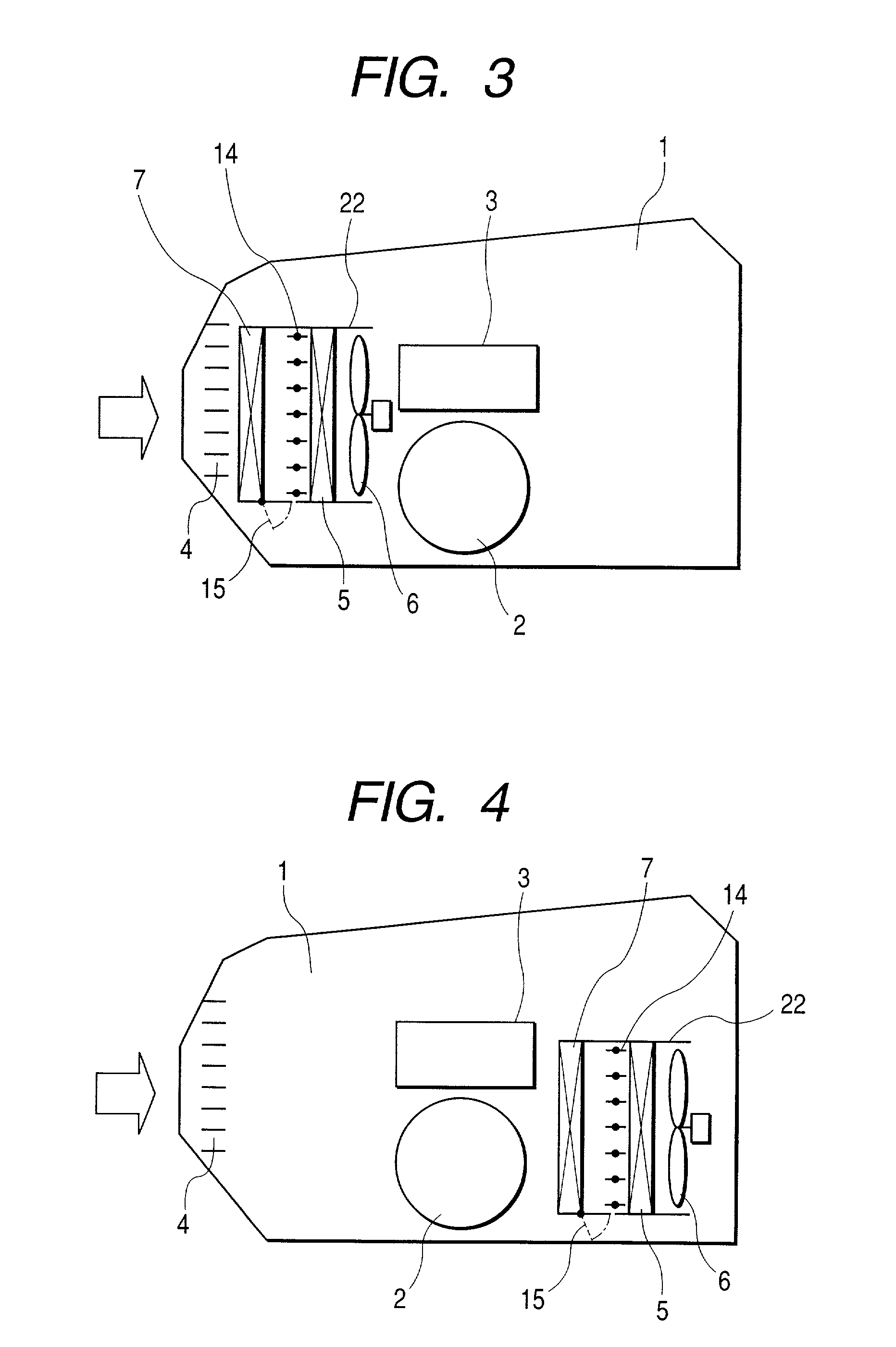
[0046] As shown by FIG. 6, a damper 16 and the exterior heat exchanger 5 are arranged in the first duct 24 and the radiator 7 and a damper 17 are arranged in a second duct 25. The two ducts 24 and 25 are contiguously provided in parallel with each other, inlet sides thereof connect to the outside air introducing grille 4 and the two ducts are provided to extend from the outside air introducing grille 4 to a rear side in the motor chamber 1. The damper 16 is provided to open and close an air flow path on the inlet side of wind blowing of the exterior heat exchanger 5 and is constituted by a plurality of sheets. A damper 17 is provided to open and close an air flow path on an outlet side of the radiator 7 and is constituted by a plurality of sheets. A path (inlet side path of the exterior heat exchanger 5) at a middle portion of the damper 16 and the exterior heat exchanger 5 and a path (outlet side path of the radiator 7) at a middle portion of the radiator 7 and the damper 17, are c...

first embodiment

[0047] In heating operation, the dampers 16 and 17 are closed and the damper 18 is opened. Thereby, outside air is inhale to the duct 25, heated by the radiator 7 and thereafter guided to the duct 24 via the damper 18 and introduced into the exterior heat exchanger 5. Thereby, waste heat of the electric apparatus can effectively be recovered to utilize and an effect the same as that of the above-described first embodiment is achieved.

[0048] Further, when rain or snow falls, outside air reaches the exterior heat exchanger 5 via the radiator 7 and therefore, rain or snow precipitates here and does not reach the exterior heat exchanger 5. Thereby, an effect the same as that of the above-described first embodiment is achieved.

[0049] In defrosting of heating operation, the damper 16 and the damper 18 are closed, the damper 17 is opened and the exterior fan 6 is stopped. Thereby, flow of air at the surrounding of the exterior heat exchanger 5 is stopped and accordingly, heat used for defr...

third embodiment

[0057] Here, an explanation will be given of a modified example of the third embodiment in reference to FIG. 9. According to the modified example shown in FIG. 9, the ducts 26 and 27 arranged with the damper 19, the exterior heat exchanger 5, the radiator 7 and the exterior fan 6, are arranged at a rear portion of the motor chamber 1 and on rear sides of the driving motor 2 and the motor driving power source 3. When rain or snow falls in heating operation, according to the embodiment shown in FIG. 8, rain or snow reaches the exterior heat exchanger 5 and attachment of frost or attachment of ice is caused and therefore, the above-described defrosting operation is needed frequently to ensure the heating capacity. When the exterior heat exchanger 5 is arranged on the rear side of the motor chamber 1 as shown by the modified example, outside air reaches the outside air heat exchanger 5 at a constant distance from the intake port 4 and therefore, during the time period, rain or snow prec...


PUM


Abstract

In an air conditioner for an automobile, restriction on arrangement of electric apparatus is removed, small-sized and light-weighted formation is achieved by promoting cooling capacity of the electric apparatus by a cooling fluid by an inexpensive constitution and firm defrosting is enabled by closing an air flow path of an exterior heat exchanger. For that purpose, there are provided a refrigeration cycle having an electrically driven compressor and an exterior heat exchanger and a radiator used in an electric automobile having a driving motor for driving the automobile and a motor driving power source for driving the driving motor and connected to cool a heat generating electric apparatus such as the driving motor or the motor driving power source via the cooling fluid, the radiator is arranged in the air flow path of exterior fan and an opening and closing apparatus for opening and closing the air flow path of the exterior heat exchanger is provided.

Description

[0001] 1. Field of the Invention[0002] The present invention relates to an air conditioner for an automobile, particularly preferable for an air conditioner used in an electric automobile driven by a driving motor.DESCRIPTION OF PRIOR ART[0003] Although a conventional air conditioner of an engine-driven automobile is generally driven by an engine, an air conditioner of an electric automobile including a hybrid automobile, is driven by electricity similar to an air conditioner for household use. Therefore, although according to the conventional engine-driven automobile, heating can be carried out by utilizing waste heat at a high temperature, according to the electric automobile, waste heat at a high temperature by engine is not be provided normally and therefore, it is necessary to carry out heating by a heat pump using a refrigeration cycle similar to the air conditioner for household use.[0004] In such an air conditioner of an electric automobile, as disclosed in Japanese Patent L...

Claims


Application Information

Patent Timeline
IPC IPC(8): B60H1/32B60K11/04B60L1/02F25B13/00B60K1/04F25D23/00
CPCB60H1/3227B60K11/04B60K2001/003B60K2001/005B60L1/003B60L2240/36F25B13/00F25B2313/02341F25B2313/02343F25B2313/02344F25D23/003B60H2001/00961B60H1/00907B60H2001/00935
Inventor MATSUO, KAZUYANAGASAWA, KIYOSHIFUKUSHIMA, TOSHIHIKO
Owner HITACHI LTD
Learn More