Virtual channels in a network switch

a virtual channel and network switch technology, applied in the field of virtual channels in network switches, can solve the problems of incompatibility of physical interface and packet format between fibre channel and ethernet, high bottlenecks in access to storage systems, and inability to meet the requirements of data transmission and storage,

Inactive Publication Date: 2003-02-06
NISHAN SYST
View PDF8 Cites 299 Cited by
  • Summary
  • Abstract
  • Description
  • Claims
  • Application Information

AI Technical Summary

Problems solved by technology

As such, access to storage systems is highly susceptible to bottlenecks.
Construction of a second high-speed network based on a different technology is a significant impediment to the proliferation of SANs.
However, the physical interface and packet formats between Fibre Channel and Ethernet are not compatible.
Too much data arriving before a device can handle it causes data overflow, meaning the data is either lost or must be retransmitted.
Because of unreliable communication (bit errors may eventually occur), packets on a link may be corrupted and as such "lost".
If packets that include credit information become corrupted, credits may be lost, potentially resulting in a deterioration of transmission rate.
It is possible that finite bit error rates may sometimes produce unreliable communication links.
On an unreliable communication link, frames carrying information about VCRDYs may be corrupted, and as such the VCRDY information may be effectively "lost".

Method used


Image

  • Virtual channels in a network switch
  • Virtual channels in a network switch
  • Virtual channels in a network switch

Examples


Embodiment Construction

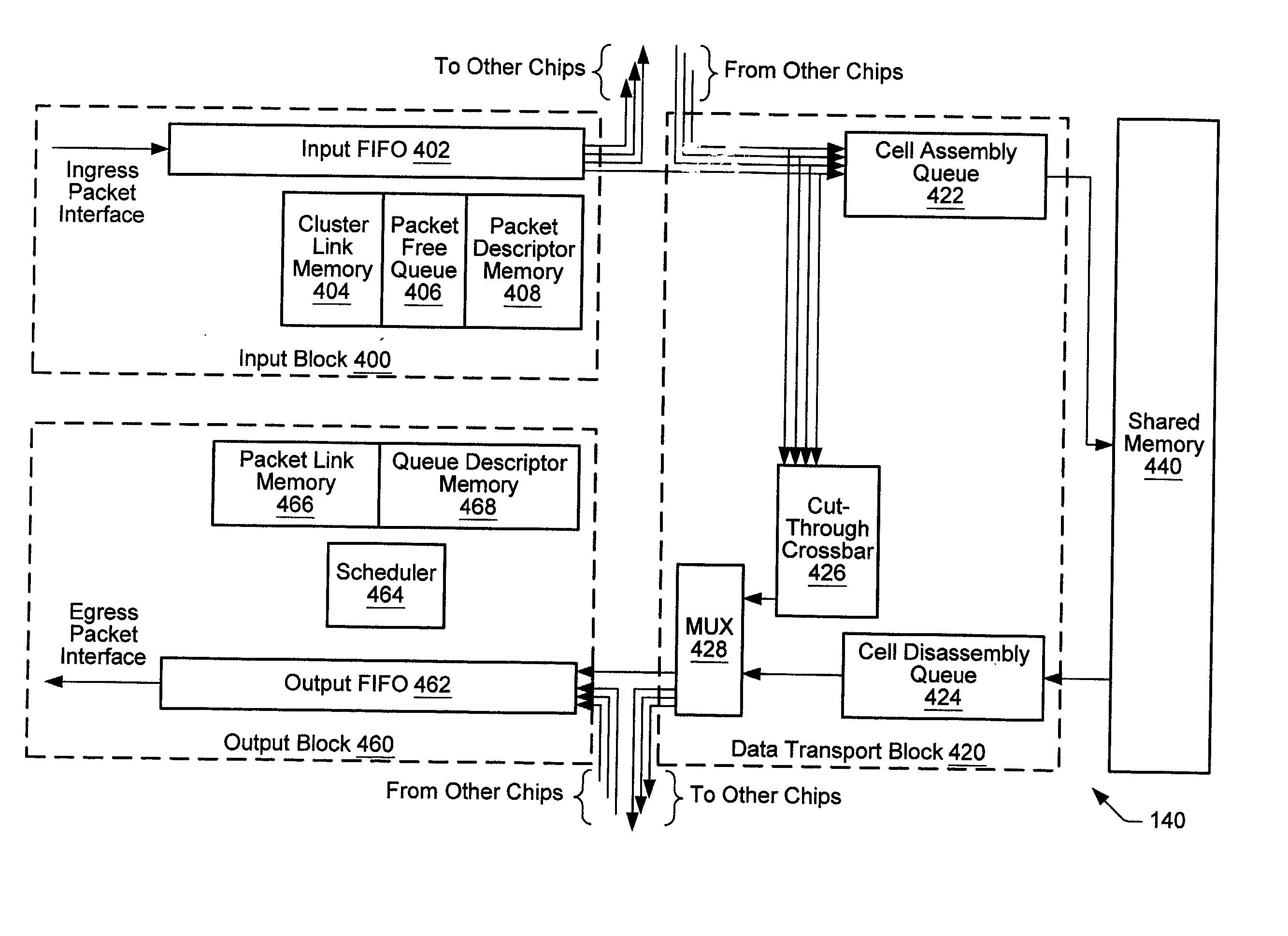
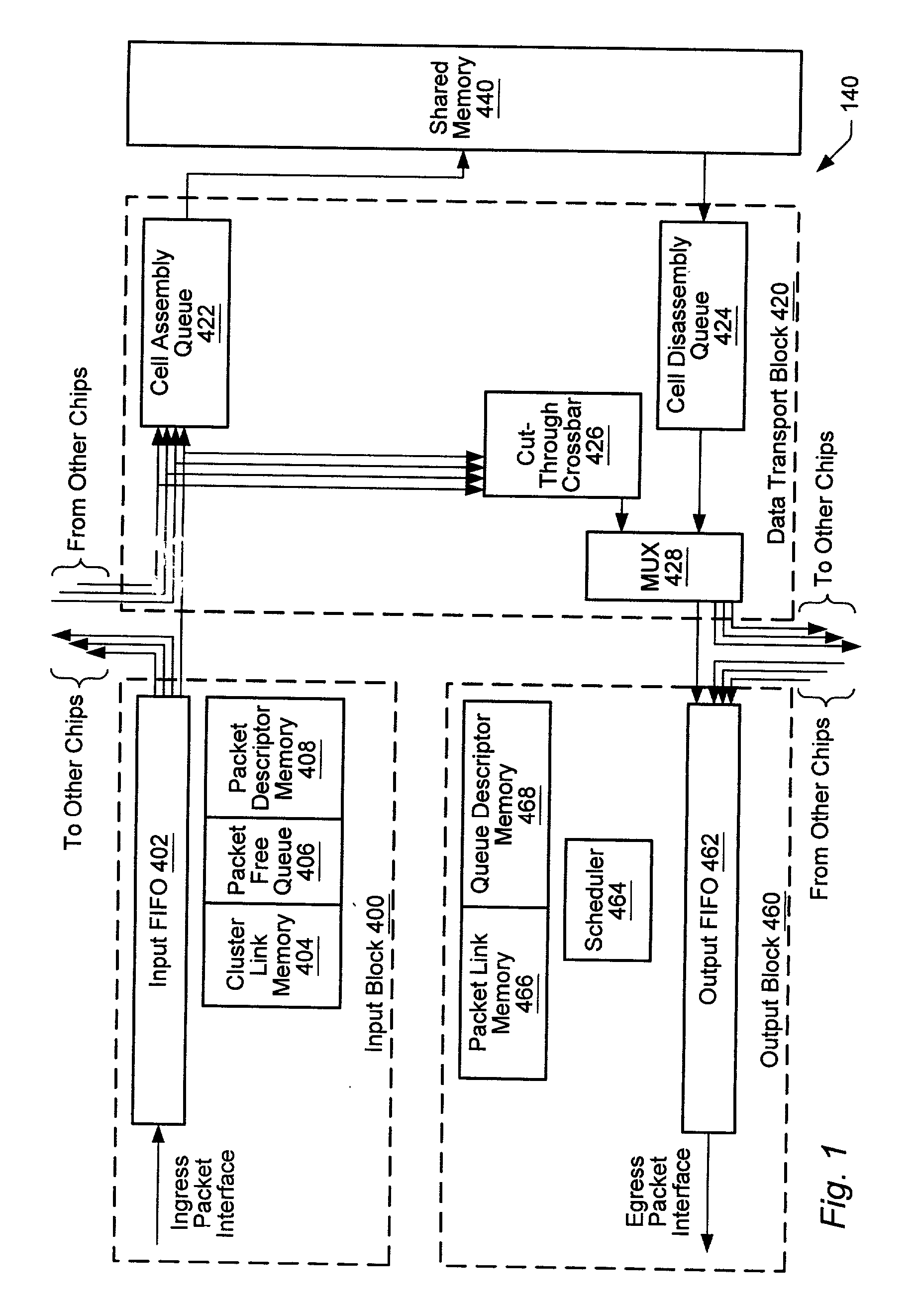
[0064] Turning now to FIG. 1, a block diagram of a portion of one embodiment of a network switch fabric is shown. In this embodiment, switch fabric portion 140 comprises an input block 400 (also referred to as an ingress block), a data transport block 420, a shared memory 440, and an output block 460 (also referred to as an egress block). The switch fabric may comprise a plurality of switch fabric portions 140 (e.g., 4 or 8 portions, each having one input port and one output port). In one embodiment, input block 400, data transport block 420 and output block 460 are all implemented on a single chip (e.g., an application specific integrated circuit or ASIC). The switch fabric may include one or more input blocks 400, wherein each input block 400 is configured to receive internal format packet data (also referred to as frames), from which it is then written into an input FIFO 402. Input block 400 may be configured to generate packet descriptors for the packet data and allocate storage...


PUM


Abstract

A system and method providing virtual channels with credit-based flow control on links between network switches. A network switch may include multiple input ports, multiple output ports, and a shared random access memory coupled to the input ports and output ports by data transport logic. Two network switches may go through a login procedure to determine if virtual channels may be established on a link. A credit initialization procedure may be performed to establish the number of credits available to the virtual channels. Credit-based packet flow may then begin on the link. A credit synchronization procedure may be performed to prevent the loss of credits due to errors. On detecting certain error conditions, a virtual channel may be deactivated. In one embodiment, the link is a Gigabit Ethernet link, and the packets are Gigabit Ethernet packets. The packets may encapsulate storage format (e.g. Fiber Channel) frames.

Description

[0001] This application claims the benefit of U.S. Provisional Application No. 60 / 309,032, filed Jul. 31, 2001.[0002] 1. Field of the Invention[0003] The present invention generally relates to the field of network switches. More particularly, the present invention relates to a system and method for providing virtual channels over links between network switches.[0004] 2. Description of the Related Art[0005] In enterprise computing environments, it is desirable and beneficial to have multiple servers able to directly access multiple storage devices to support high-bandwidth data transfers, system expansion, modularity, configuration flexibility, and optimization of resources. In conventional computing environments, such access is typically provided via file system level Local Area Network (LAN) connections, which operate at a fraction of the speed of direct storage connections. As such, access to storage systems is highly susceptible to bottlenecks.[0006] Storage Area Networks (SANs) ...

Claims


Application Information

Patent Timeline
Patent Type & Authority Applications(United States)
IPC IPC(8): H04L12/56
CPCH04L12/5601H04L47/10H04L47/16H04L47/2441H04L47/39H04L49/101H04L49/3036H04L49/3072H04L49/351H04L49/354H04L49/90
Inventor OBERMAN, STUART F.MEHTA, ANILMULLENDORE, RODNEY N.MALIK, KAMRANSCHAKEL, KEITH
Owner NISHAN SYST
Why Eureka
Try Eureka