Usage monitoring HVAC control system

a programmable hvac and control system technology, applied in the direction of program control, static/dynamic balance measurement, instruments, etc., can solve the problems of large energy wastage, large energy consumption of heating ventilation and air conditioning systems, and inability to provide,

Inactive Publication Date: 2003-02-27
MMI CONTROLS
View PDF19 Cites 39 Cited by
  • Summary
  • Abstract
  • Description
  • Claims
  • Application Information

AI Technical Summary

Problems solved by technology

Heating, ventilation, and air conditioning (HVAC) systems consume a large amount of energy.
Since many buildings may be unoccupied for certain periods of time, the continuous operation of such conventional HVAC systems would result in wastage of a large amount of energy.
Such provision is often impractical since most buildings do no

Method used


Image

  • Usage monitoring HVAC control system
  • Usage monitoring HVAC control system
  • Usage monitoring HVAC control system

Examples


Embodiment Construction

[0018] The invention and the various features and advantageous details thereof are explained more fully with reference to the nonlimiting embodiments that are illustrated in the accompanying drawings and detailed in the following description. Descriptions of well known components and processing techniques are omitted so as not to unnecessarily obscure the invention in detail. It should be understood, however, that the detailed description and the specific examples, while indicating preferred embodiments of the invention, are given by way of illustration only and not by way of limitation. Various substitutions, modifications, additions and / or rearrangements within the spirit and / or scope of the underlying inventive concept will become apparent to those skilled in the art from this detailed description.

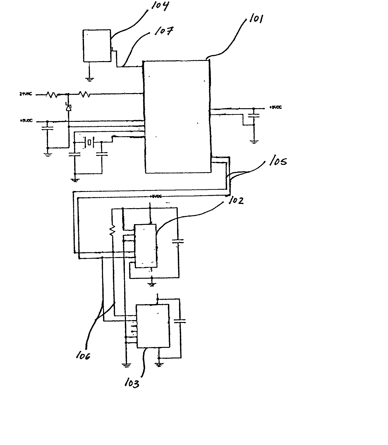
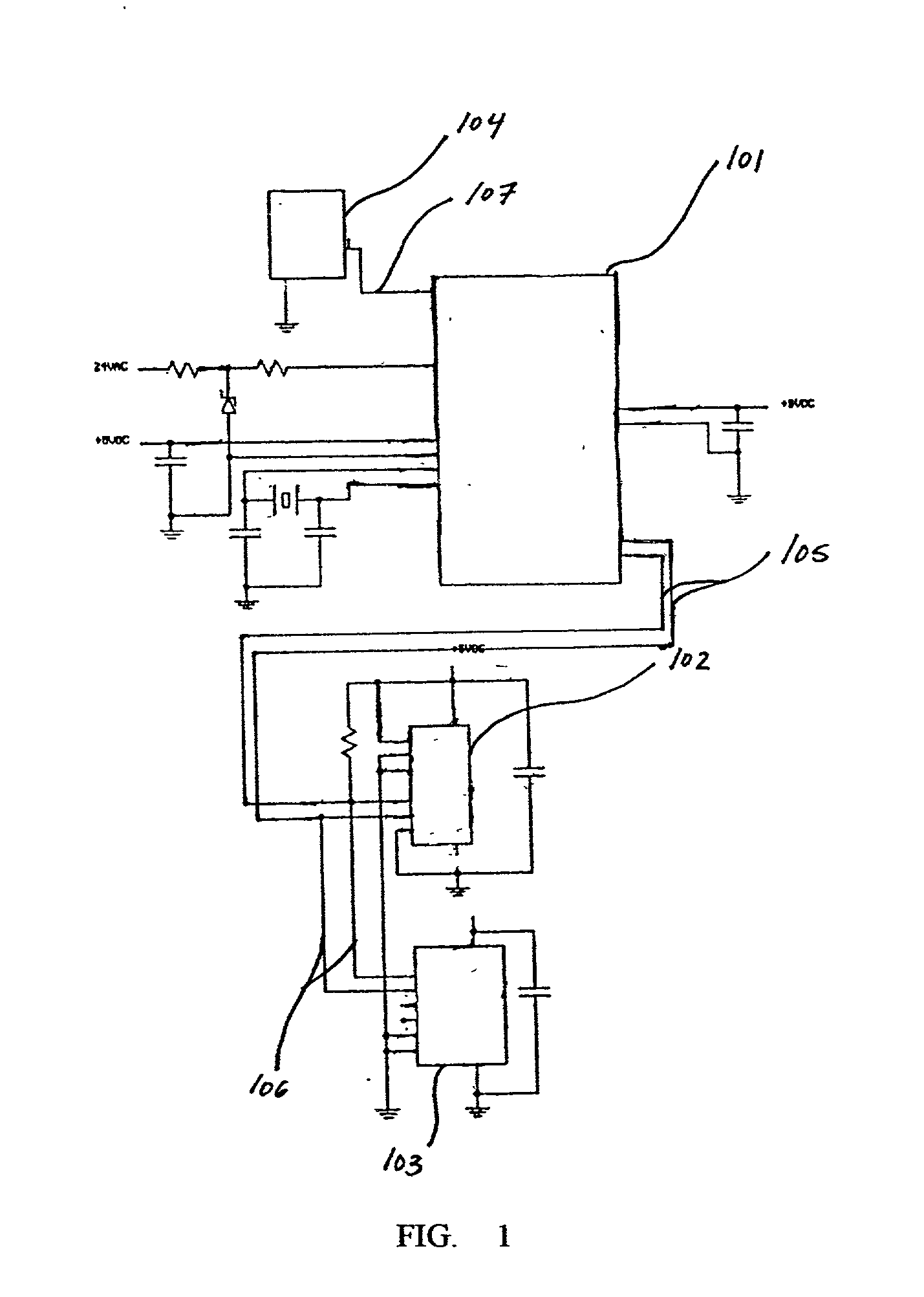
[0019] The context of the invention can include commercial buildings where a plurality of users require HVAC system services. The context of the invention can also include residential b...


PUM


Abstract

Systems and methods are described for a usage monitoring HVAC control system. A method, includes: providing a usage monitoring heating ventilation and air conditioning control system, the usage monitoring heating ventilation and air conditioning control system including a programmable digital thermostat with an on board memory; issuing personal identification numbers to each of a plurality of system users; associating each of the plurality of system users with at least one of a plurality of user types; storing the personal identification numbers in a first data structure in the on board memory; and linking each one of a plurality of entries in the first data structure by reference to at least one of a plurality of entries in a second data structure in the on board memory, the second data structure including a list of user types. A method, includes: receiving a request for an additional period of heating ventilation and air conditioning system services from a requesting system user, the requesting system user composing a plurality of system users; maintaining a data structure in an on board memory of a programmable thermostat, the data structure including a list of time entries, each time entry associated with one of the plurality of system users; and updating the data structure by adding a duration in units of time to the time associated with the requesting system user. An apparatus, includes: a microcontroller; a digital temperature sensor coupled to the microcontroller; a liquid crystal display coupled to the microcontroller; a set of cursor buttons coupled to the microcontroller; an electrically erasable programmable read-only memory coupled to the microcontroller; an upload capable connector coupled to the electronically erasable programmable read-only memory; a real time clock coupled to the microcontroller; and a back up power supply coupled to the real time clock. A method, includes regulating user access to an interactive user interface of a programmable thermostat, each user identified by a personal identification number associated with a user type selected from the group consisting of building owners, maintenance personnel, building tenants, and manufacturers.

Description

[0001] 1. Field of the Invention[0002] The invention relates generally to the field of programmable heating, ventilation, and air conditioning (HVAC) systems. More particularly, the invention relates to energy saving programmable HVAC systems. Specifically, a preferred implementation of the invention relates to a usage monitoring programmable HVAC system.[0003] 2. Discussion of the Related Art[0004] Heating, ventilation, and air conditioning (HVAC) systems consume a large amount of energy. Commonly, heating and cooling operations are controlled automatically with a thermostat or plurality of thermostats which initiate these operations according to preset temperature limits. The thermostat can be located at a predetermined central local or the plurality of thermostats can be located at a predetermined plurality of locations. The thermostats are capable of detecting changes in room temperature. When the room temperature fluctuates outside the preset high and low temperature limits, th...

Claims


Application Information

Patent Timeline
IPC IPC(8): G05B23/02
CPCF24F11/0086F24F2011/0094G05B15/02G05B2219/2642G06Q50/06F24F11/30F24F11/47Y02P80/10F24F11/46
Inventor POTH, ROBERT J.
Owner MMI CONTROLS
Why Eureka
Try Eureka