Gas turbine blade cooling circuits

Inactive Publication Date: 2003-03-06
SN DETUDE & DE CONSTR DE MOTEURS DAVIATION S N E C M A
View PDF0 Cites 33 Cited by
  • Summary
  • Abstract
  • Description
  • Claims
  • Application Information

AI Technical Summary

Benefits of technology

0007] The present invention thus seeks to mitigate those drawbacks by proposing improvements to gas turbine blades, and more particularly to the cooling

Problems solved by technology

This has the consequence of incre

Method used


Image

  • Gas turbine blade cooling circuits
  • Gas turbine blade cooling circuits
  • Gas turbine blade cooling circuits

Examples


Example

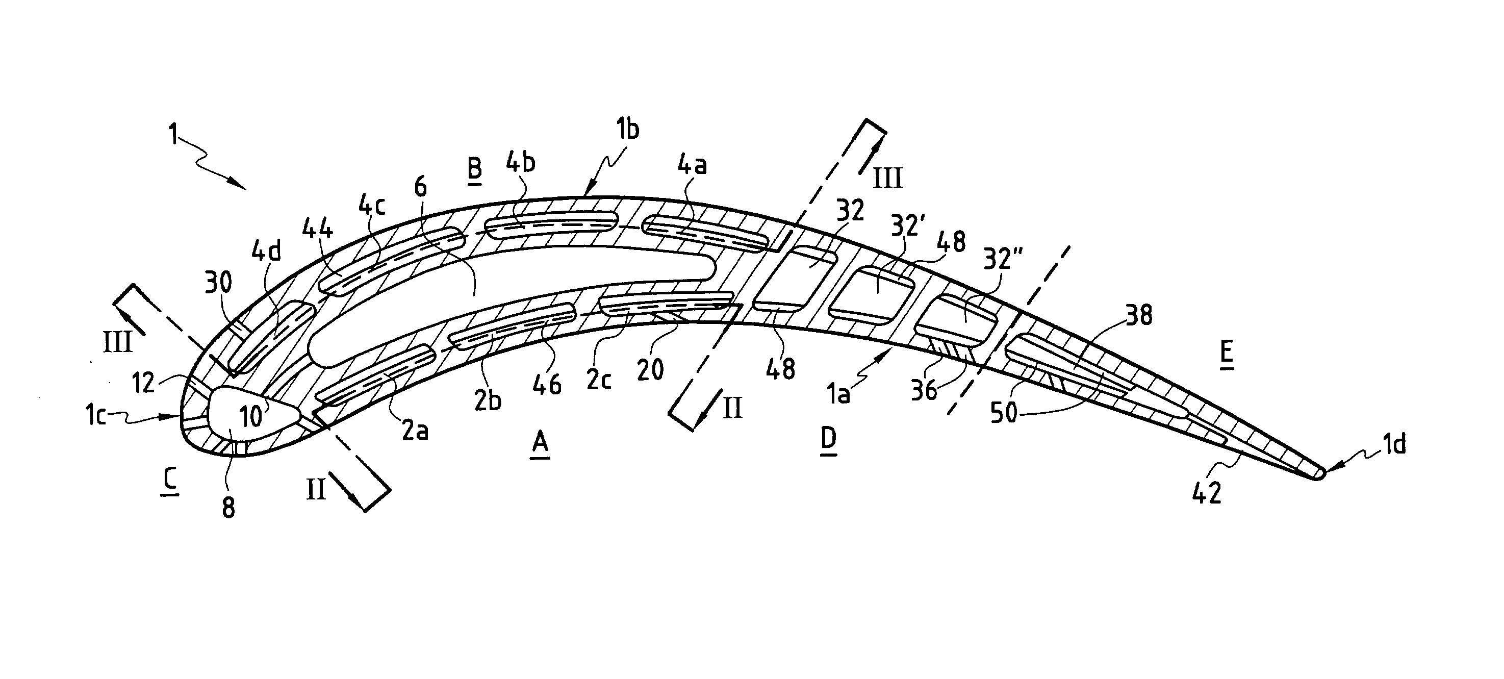
[0018] With reference to FIG. 1, it can be seen that the blade 1 of a gas turbine of an airplane engine constituting an embodiment of the invention comprises, in its central portion, first and second cooling circuits A and B respectively that are independent from each other. The first circuit A comprises at least one cavity on the concave side and preferably a plurality of cavities, for example three concave side cavities 2a, 2b, and 2c extending radially beside the concave face 1a of the blade 1. The second cooling circuit B comprises at least one convex side cavity, and preferably a plurality, for example four convex side cavities 4a to 4d, extending radially beside the convex face 1b of the blade.

[0019] These circuits serve to cool respectively the concave face and the convex face of the blade 1 in a mode of operation that is described in greater detail below.

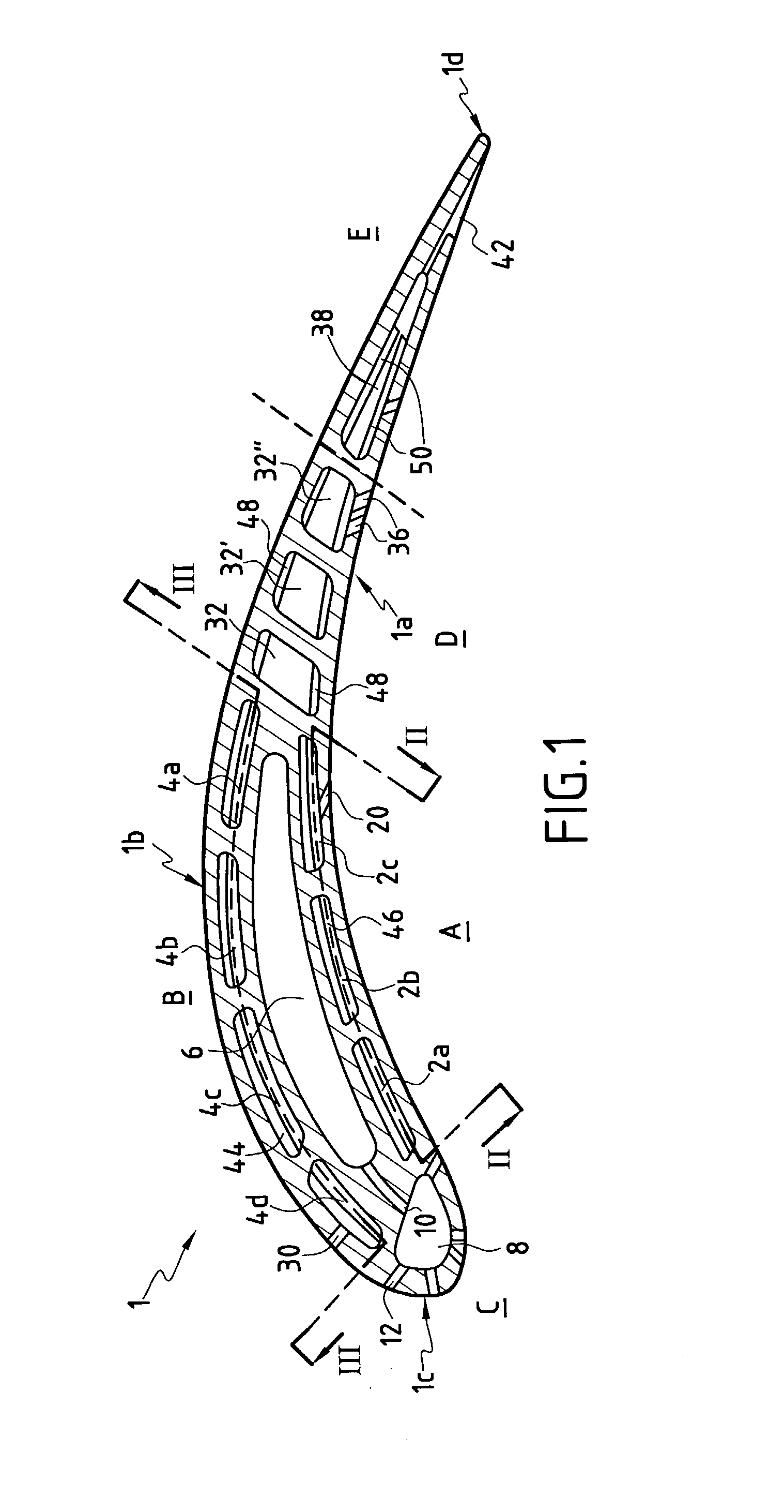
[0020] As shown more precisely in FIG. 2, an air admission opening 14 is provided at a radial end of a concave side cavity...


PUM


Abstract

A gas turbine blade for an airplane engine, the blade comprising at least a first cooling circuit comprising at least a concave side cavity extending radially beside the concave face of the blade, at least a second cooling circuit comprising at least one convex side cavity extending radially beside the convex face of the blade, and at least one third cooling circuit comprising at least one central cavity situated in the central portion of the blade between the concave side cavity and the convex side cavity, at least one leading edge cavity situated in the vicinity of the leading edge of the blade, communication orifices opening out into the central cavity and into the leading edge cavity, and outlet orifices opening out into the leading edge cavity and through the leading edge of the blade.

Description

[0001] The present invention relates to improvements made to gas turbine blades for an airplane engine. More particularly, the invention relates to the cooling circuits of such blades.[0002] It is known that the moving blades of an airplane engine gas turbine, and in particular of the high pressure turbine, are subjected to very high temperatures from combustion gases when the engine is in operation. These temperatures reach values that are well above those that can be withstood without damage by the various pieces that come into contact with these gases, thereby limiting the lifetime of such pieces.[0003] Furthermore, it is known that raising the temperature of the gases in a high pressure turbine improves the efficiency of an engine, and thus the ratio of engine thrust over the weight of an airplane propelled by the engine. Consequently, efforts are made so as to provide turbine blades that are capable of withstanding higher and higher temperatures.[0004] In order to solve this pr...

Claims


Application Information

Patent Timeline
IPC IPC(8): F01D5/18
CPCF01D5/186F01D5/187Y02T50/67Y02T50/676F05D2260/2212Y02T50/60
Inventor BOURRIAUD, ISABELLEENEAU, PATRICEPICOT, PHILIPPE
Owner SN DETUDE & DE CONSTR DE MOTEURS DAVIATION S N E C M A
Why Eureka
Try Eureka