Tool, a machine tool, and a method of cutting

Inactive Publication Date: 2003-03-13
NOVATOR
View PDF9 Cites 7 Cited by
  • Summary
  • Abstract
  • Description
  • Claims
  • Application Information

AI Technical Summary

Benefits of technology

[0012] By means of a tool having such a lateral main cutting edge, a workpiece surface, which is substantially parallel to the longitudinal centre axis, may be machined by the milling operation defined in such a way that a high surface fineness is obtained. Furthermore, the tool creates possibilities to perform the machining in a relatively short time, for instance in a so-called HSM-machine (High Speed Machining). In addition, the same tool may be used for a large number of different machining situations, for instance for machining of holes having different hole diameters.
[0013] According to an advantageous embodiment of the invention, said main cutting edge in the direction of a centre axis has an extension which is relatively short in relation to the axial length of the tool shaft. By such a short main cutting edge, the tool is relatively simple and may thus be manufactured to a low cost. Thereby, the main cutting edge may in the direction of the centre axis have an extension, which is relatively short in an axial direction in relation to the length of the workpiece, which the tool is intended to machine. A complete machining of the workpiece surface may be obtained by feeding the tool in the direction of the longitudinal centre axis.
[0017] According to a further embodiment of the invention, said main cutting edge is rounded at its axial outer end. Thereby, a high strength of the tool is obtained. In the same way, said main cutting edge may also be rounded at its axial inner end.
[0018] According to a further advantageous embodiment of the invention, the tool includes a coolant channel for the supply of a coolant, wherein the coolant channel extends through the tool shaft substantially concentrically with the centre axis. By such a coolant channel, a long life of the tool may be obtained and furthermore an efficient removal of chips is ensured in all different types of machining. The coolant channel may extend through the end surface.

Problems solved by technology

However, the machining by such tools is very time-consuming, in particular if a high accuracy is aimed at.

Method used


Image

  • Tool, a machine tool, and a method of cutting
  • Tool, a machine tool, and a method of cutting
  • Tool, a machine tool, and a method of cutting

Examples


Embodiment Construction

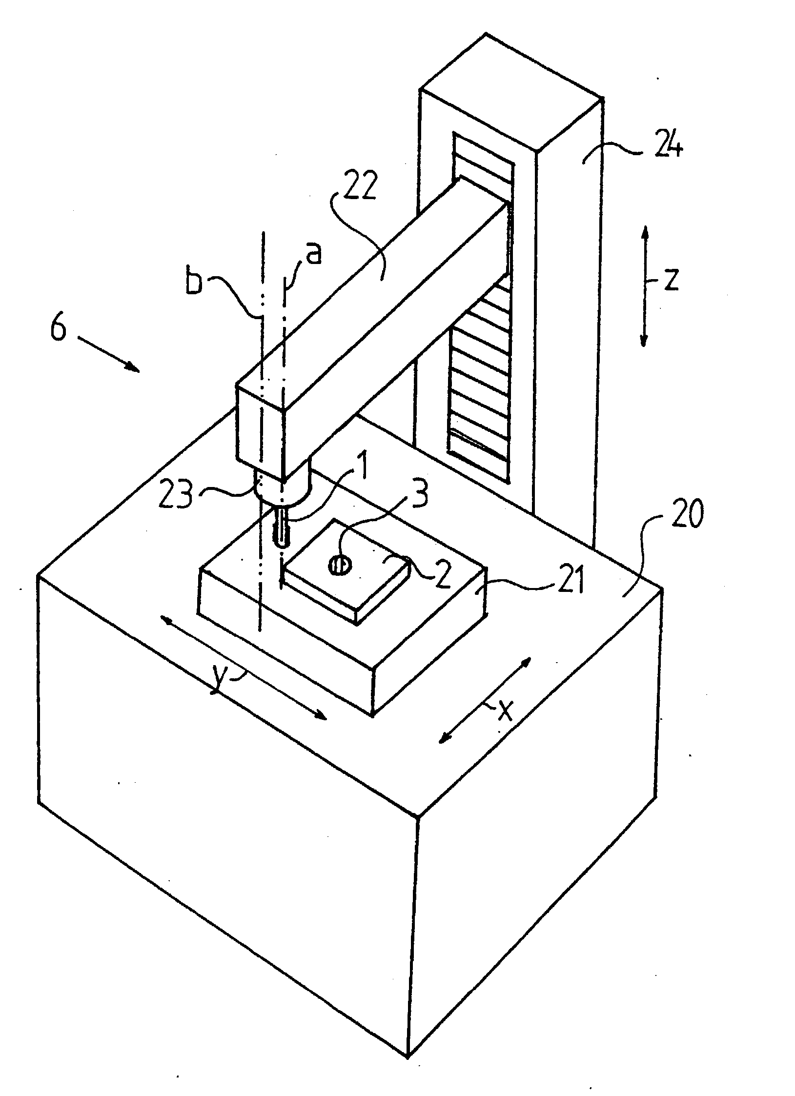
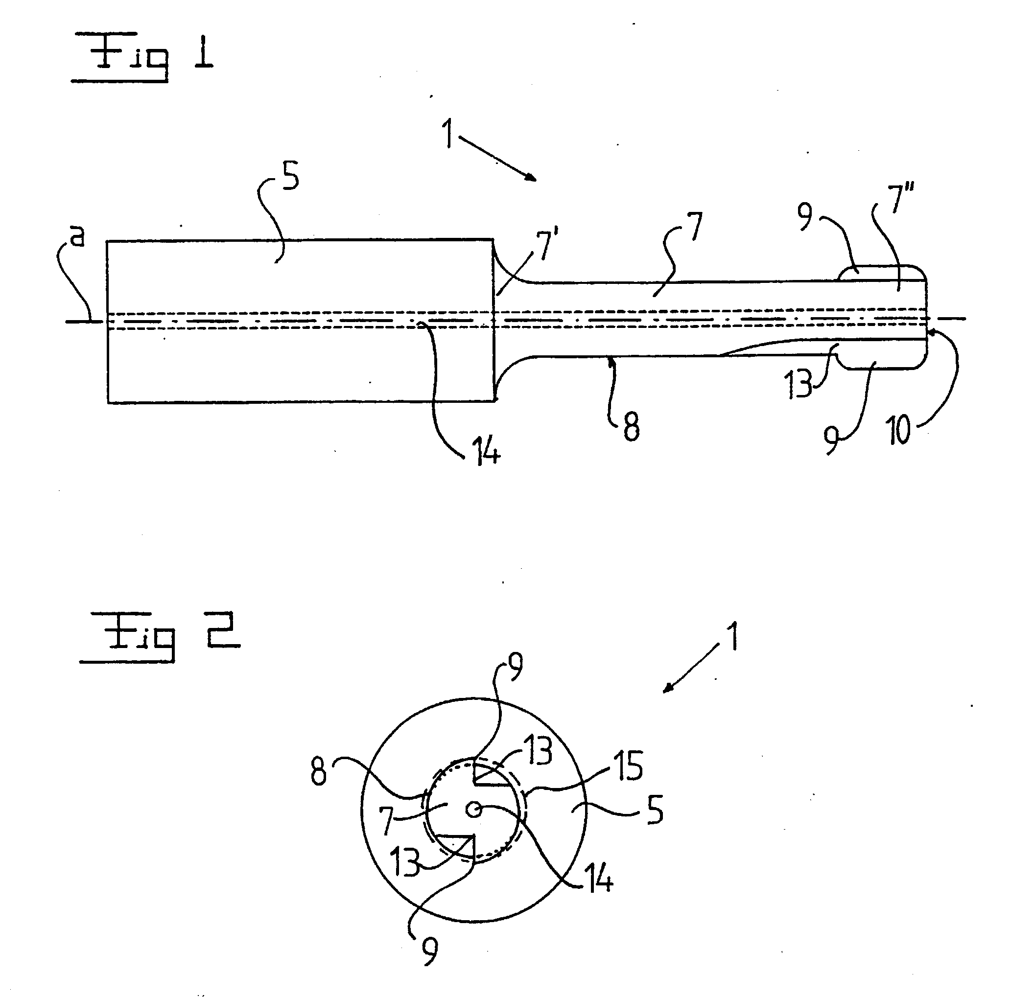
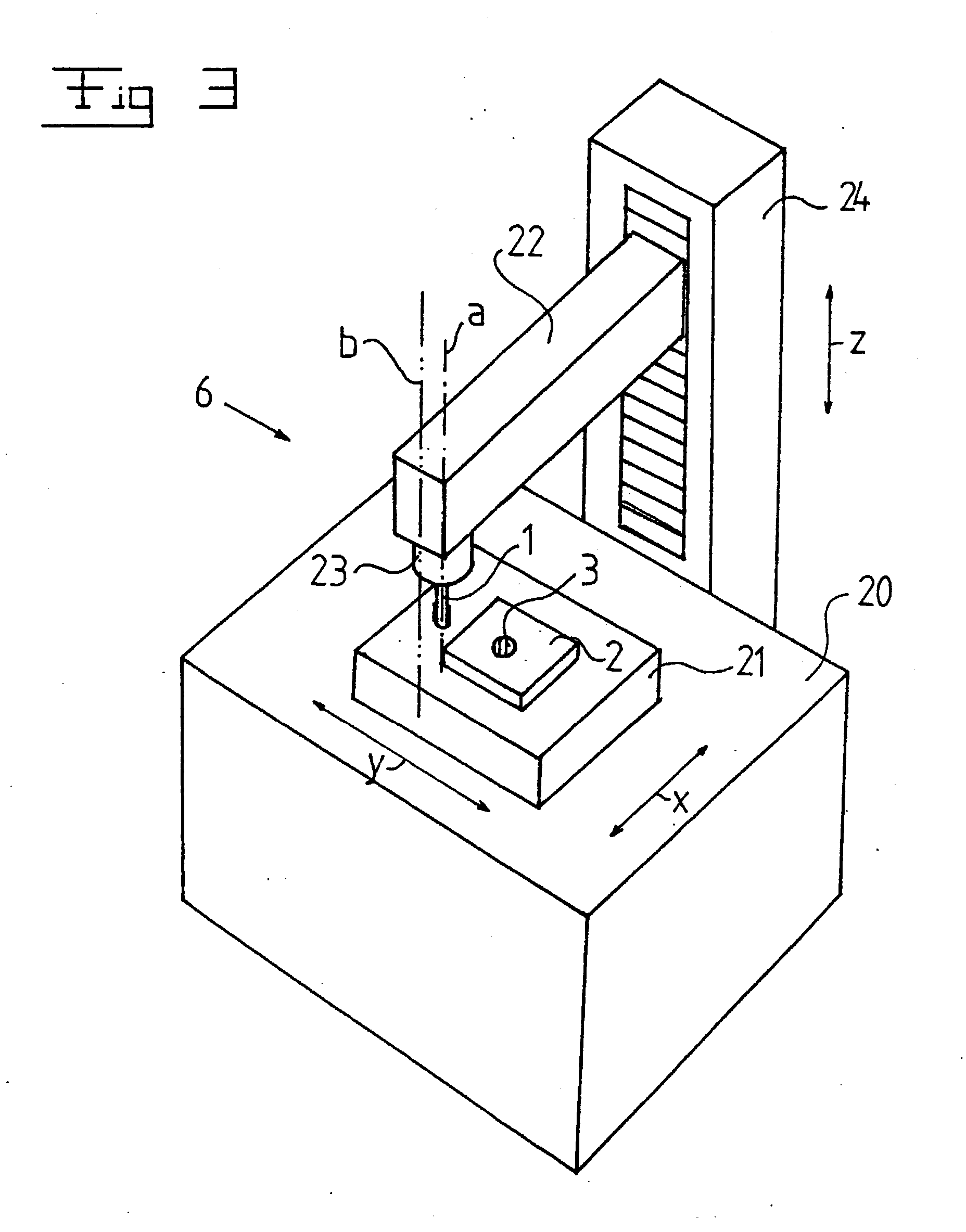
[0036] FIGS. 1 and 2 disclose a tool 1 for cutting machining of a workpiece 2, see FIG. 3. The tool 1 is in particularly intended for finishing machining of the cylindrical limiting wall of a hole 3 in the workpiece 2. Such holes 3 may have different cross-sectional shapes and for instance be cylindrical or oval. The tool 1 according to the invention may also be used for machining a concave limiting wall of a recess, which extends inwardly from a side surface of a workpiece 2.

[0037] The tool 1 includes a mounting portion 5, which is arranged to permit mounting of the tool 1 in a machine tool 6, see FIG. 3. The mounting portion 5 is substantially circular cylindrical. Furthermore, the tool 1 includes a tool shaft 7, which has a first inner end 7' and a second outer end 7". The tool shaft 7 is at its first inner end 7' connected to the mounting portion 5. The tool shaft 7" also has a substantially circular cylindrical shape, i.e. the tool shaft 7 has a substantially circular cylindric...


PUM

PropertyMeasurementUnit
Angleaaaaaaaaaa
Angleaaaaaaaaaa
Lengthaaaaaaaaaa

Abstract

The invention refers to a tool (1), a machine tool, and a method for cutting machining of a workpiece. The tool includes a mounting portion (5) for mounting of the tool in the machine tool, a tool shaft (7), which has a first inner end (7'), connected to the mounting portion (5), a longitudinal centre axis (a), which extends through the mounting portion and the tool shaft, and a main cutting edge (9) on the tool shaft. The main cutting edge (9) has an extension in an axial direction along an imaginary envelope surface, which is concentric to the centre axis (a) and located radially outside an outer periphery surface of the tool shaft (7). The main cutting edge (9) is arranged to permit cutting engagement with said workpiece when the tool is rotated around the longitudinal centre axis.

Description

THE BACKGROUND OF THE INVENTION AND PRIOR ART[0001] The present invention refers to a tool for cutting machining of a workpiece, comprising a mounting portion, which is arranged to permit mounting of the tool in a machine tool, a tool shaft, which has a first inner end, connected to the mounting portion, and a second outer end, a longitudinal centre axis, which extends through the mounting portion and the tool shaft, and at least one main cutting edge, which is provided on the tool shaft. The invention also refers to a machine tool for cutting machining of a workpiece, including a tool, which comprises[0002] a mounting portion by which the tool is mounted in the machine tool,[0003] a tool shaft, which has a first inner end, connected to the mounting portion, and a second outer end,[0004] a longitudinal centre axis, which extends through the mounting portion and the tool shaft, and[0005] at least one main cutting edge, which is provided on the tool shaft,[0006] first means arranged t...

Claims


Application Information

Patent Timeline
IPC IPC(8): B23D77/00
CPCB23D77/006Y10T409/307616Y10T407/1948Y10T409/304424Y10T409/304032Y10T409/303808Y10T83/0567
Inventor HAVSKOG, NILS-ERIK
Owner NOVATOR
Why Eureka
Try Eureka