System and method for effecting high-power beam control with adaptive optics in low power beam path

a technology of adaptive optics and beam path, applied in the field of optics, can solve the problems of reducing durability and/or increasing manufacturing cost, affecting the performance of conventional adaptive optics systems using deformable mirrors, and delicate optical devices in the path of high-power beams

Inactive Publication Date: 2003-04-03
RAYTHEON CO
View PDF16 Cites 64 Cited by
  • Summary
  • Abstract
  • Description
  • Claims
  • Application Information

AI Technical Summary

Problems solved by technology

Unfortunately, the use of delicate optical devices in the path of a high-power beam is problematic.
Therefore, coatings may need to be applied at lower than optimal temperature using more complex coating processes, thereby reducing durability and/or increasing manufacturing cost.
In addition, conventional adaptive optics systems using deformable mirrors are limited in performance.
There is also a limitation with respect to the number actuators that can be used.
The stroke of the conventional deformable mirror is limited.
Further, a conventional continuous face sheet deformable mirror cannot correct for a pathology in the spatial phase pattern, such as a branch point ...

Method used


Image

  • System and method for effecting high-power beam control with adaptive optics in low power beam path
  • System and method for effecting high-power beam control with adaptive optics in low power beam path
  • System and method for effecting high-power beam control with adaptive optics in low power beam path

Examples


Embodiment Construction

[0025] Illustrative embodiments and exemplary applications will now be described with reference to the accompanying drawings to disclose the advantageous teachings of the present invention.

[0026] While the present invention is described herein with reference to illustrative embodiments for particular applications, it should be understood that the invention is not limited thereto. Those having ordinary skill in the art and access to the teachings provided herein will recognize additional modifications, applications, and embodiments within the scope thereof and additional fields in which the present invention would be of significant utility.

[0027] 1. Conventional HEL Beam Control Architectures

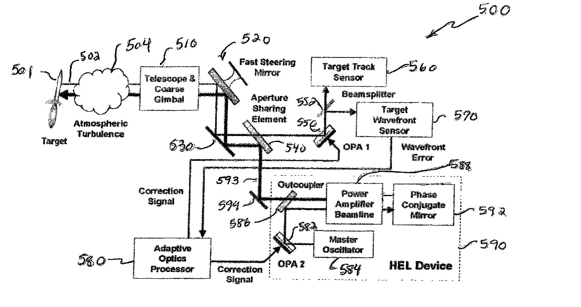
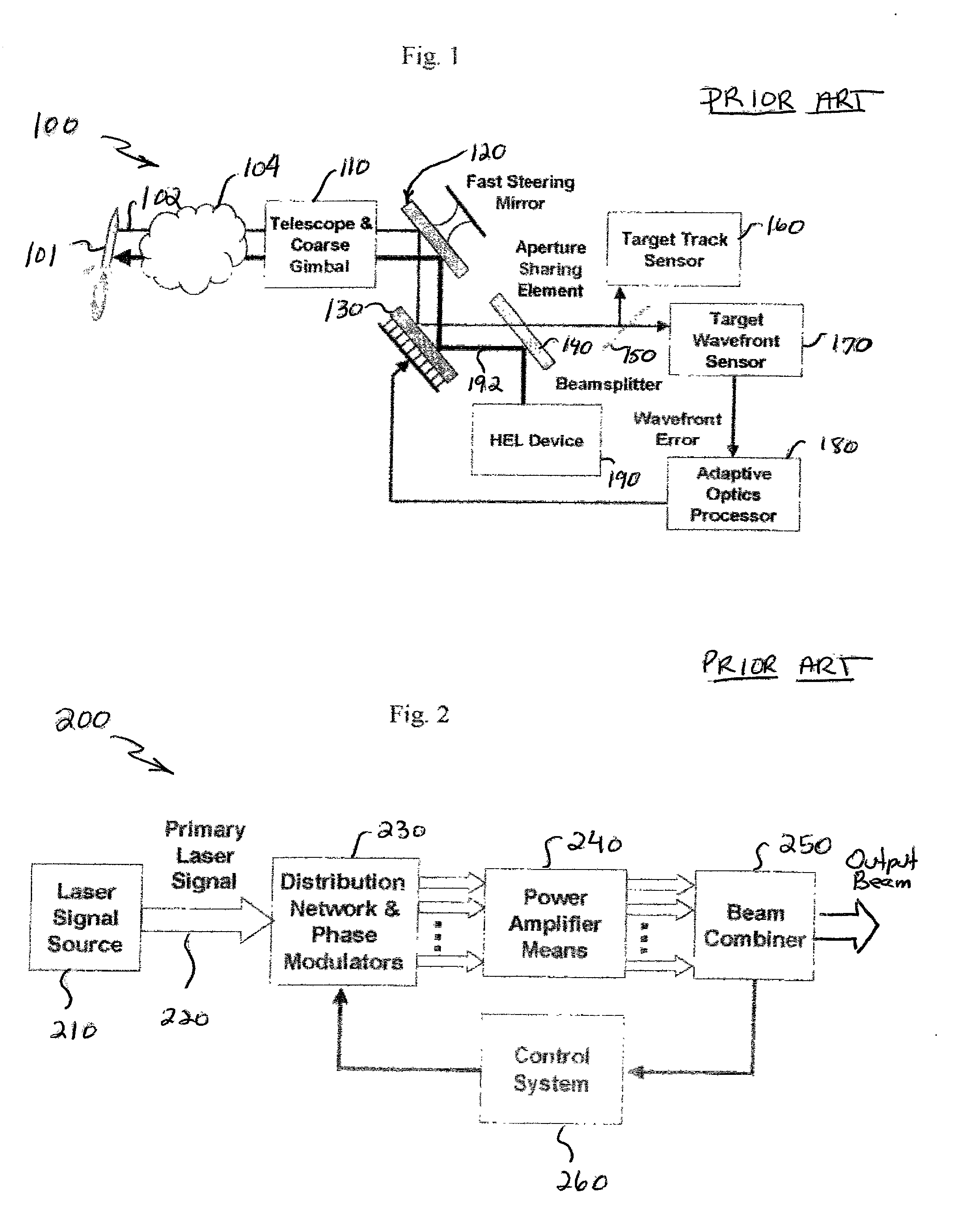
[0028] A simplified optical schematic of a conventional High Energy Laser (HEL) beam control architecture 100 is shown in FIG. 1. A HEL beam director, generally consisting of a Telescope and multi-axis Coarse Gimbal 110, is commanded to the line-of-sight of a Target 101 based on an external cue (...


PUM


Abstract

A beam control system and method which utilizes the wavefront reversal property of nonlinear optical phase conjugation to permit incorporation of a liquid crystal OPA within the low power legs of the beam control system, thereby affording the advantages of the OPA without the power limitations thereof. The invention is adapted for use with a beacon for illuminating a target with a first beam of electromagnetic energy. The system includes a telescope (1010) for receiving a target return comprising a reflection of the first beam from the target. An optical phased array (1050) is included for correcting for aberrations in the wavefront of the target return. A mechanism is included for ascertaining the correction applied by the optical phased array to the target return. The mechanism applies the correction to a third beam which ultimately is the output beam. In the illustrative embodiment, the first beam of electromagnetic energy is optical energy and the mechanism includes a first phase conjugate mirror (1091) adapted to conjugate electromagnetic energy output by the third mechanism and a second phase conjugate mirror (1092) adapted to conjugate the output of the first phase conjugate mirror. The fourth mechanism further includes an amplifier (1088) for boosting the signal output by the second phase conjugate mirror (1092) to provide the output beam.

Description

[0001] 1. Field of the Invention[0002] The present invention relates to optics. More specifically, the present invention relates to systems and methods for directing and correcting high-power beams of electromagnetic energy.[0003] 2. Description of the Related Art[0004] Directed energy weapons and specifically high-energy laser (HEL) weapons are being considered for variety of military applications with respect to a variety of platforms, e.g., spaceborne, airborne and land based systems to name a few. These weapons generally involve the use of the laser or other source of a high-power beam to track and destroy a target. To achieve mission objectives, directed energy weapons must be accurately steered and optimally focused. Steering involves line-of-sight control while focusing, with respect to HEL weapons, involves wavefront error correction. Currently, wavefront error correction is typically achieved using adaptive optics. The current state of the art in laser beam control adaptive...

Claims


Application Information

Patent Timeline
IPC IPC(8): G02B26/06G02B27/00
CPCF41H13/0043G02B27/4233G02B27/0037G02B26/06
Inventor BYREN, ROBERT W.TRAFTON, ALVIN F.
Owner RAYTHEON CO
Why Eureka
Try Eureka