Switching methodology for ground referenced voltage controlled electric machine

Inactive Publication Date: 2003-04-03
DELPHI TECH INC
View PDF73 Cites 49 Cited by
  • Summary
  • Abstract
  • Description
  • Claims
  • Application Information

AI Technical Summary

Benefits of technology

0011] Disclosed is a system for dead time switching in a sinusoidally excited PM electric machine. The system comprises: a PM electric machine; a position sensor configured to measure a position of the electric machine and transmit a position signal; and a controller, where the controller receives the position signal. The controller executes a method comprising: obtaining a duty cycle command; generating a first control comm

Problems solved by technology

Therefore, electric power steering typically requires power only on demand.
However, due to practical limitations of motor design and controller implementation, there are always deviations from pure sinusoidal back EMF and current waveforms.
Such deviations usually result in parasitic torque ripple components at various frequencies and magnitudes.
This dead time during which both the switching devices are

Method used


Image

  • Switching methodology for ground referenced voltage controlled electric machine
  • Switching methodology for ground referenced voltage controlled electric machine
  • Switching methodology for ground referenced voltage controlled electric machine

Examples


Embodiment Construction

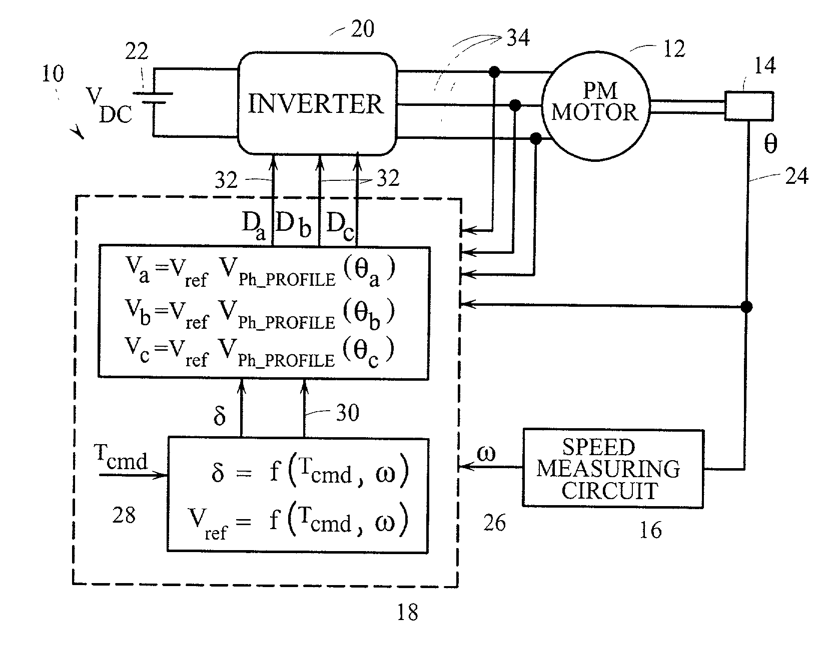
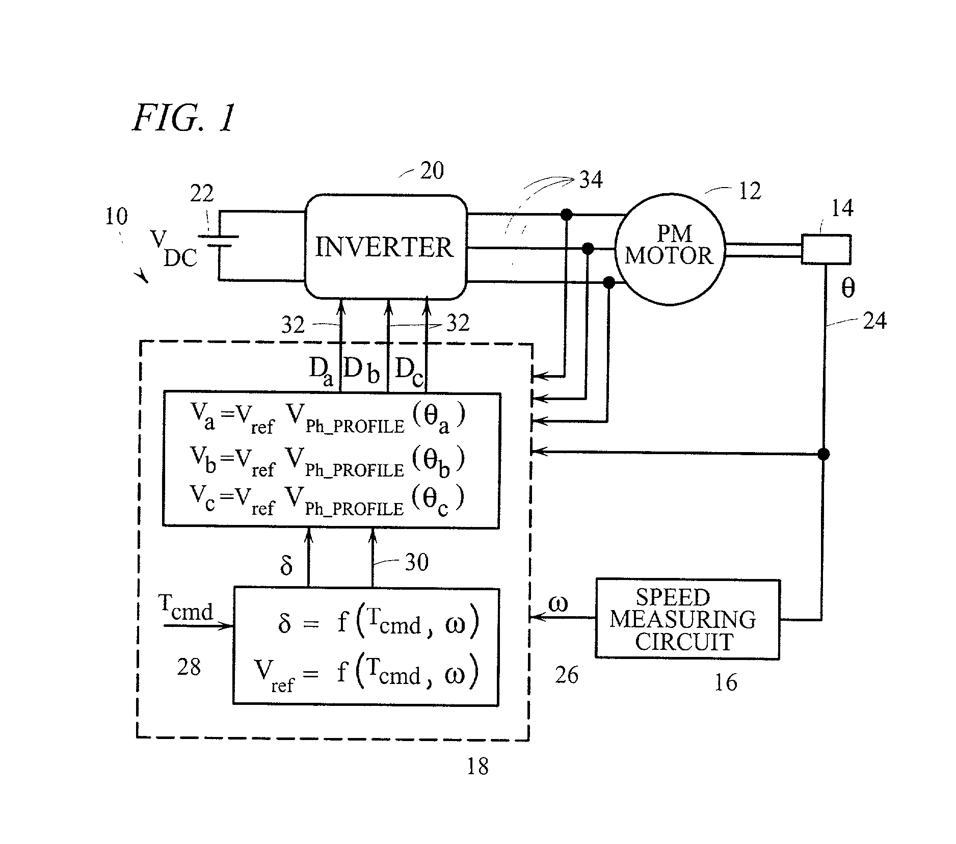
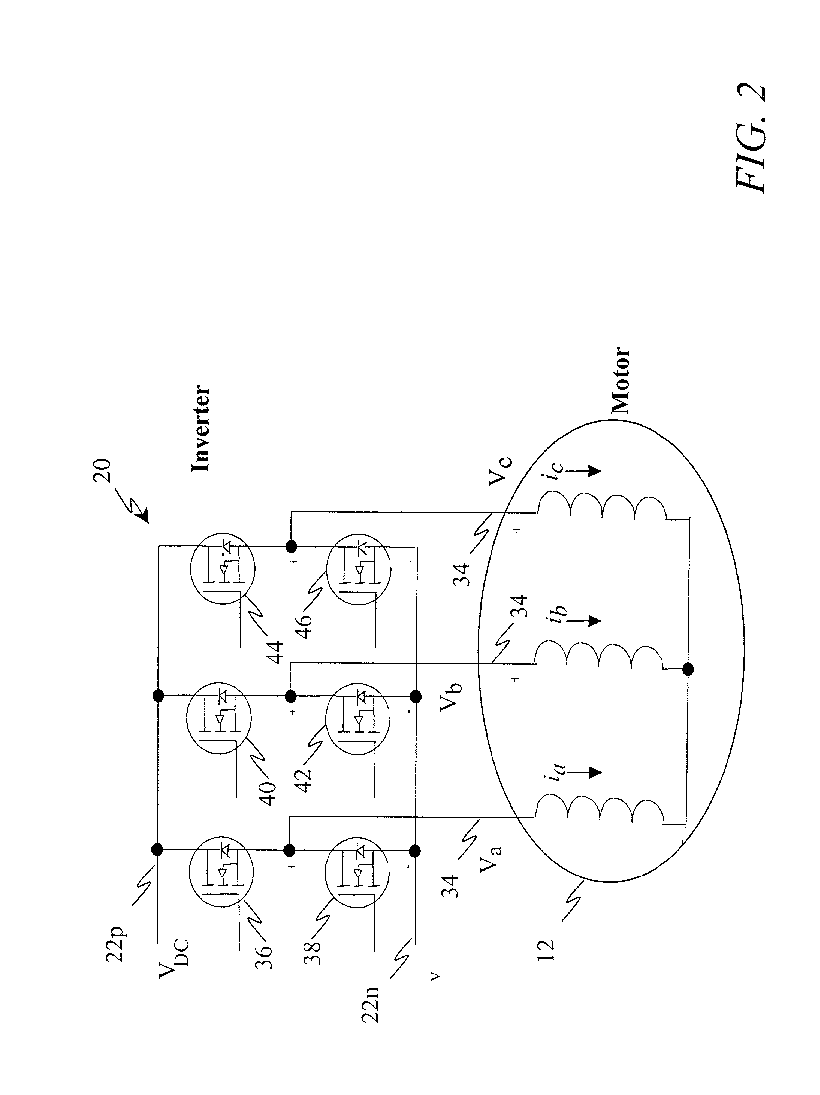
[0033] Disclosed herein in an exemplary embodiment is a system and method for applying dead time to switching in a PWM motor control. In an exemplary embodiment, the dead time is applied to the control of a selected upper switching device for a selected, motor phase. The upper switching device(s) are connected between the positive terminal of DC bus 22p and the motor phase. Delaying the turn on and advancing the turn off of the upper switching devices achieves the dead time control. Because there is no dead time applied to the lower switching devices, the nonlinearity at the point when the phase current lifts off from the ground as evidenced with conventional switching does not appear. Therefore, as there is no loss of voltage before or after the voltage lift, the three per electric revolution torque ripple is considerably reduced.

[0034] Referring now to the drawings in detail, FIGS. 1 and 2 depict a PM motor system 10 as may be employed to implement an exemplary embodiment disclose...


PUM


Abstract

Disclosed is a system for dead time switching in a sinusoidally excited PM electric machine. The system comprises: a PM electric machine; a position sensor configured to measure a position of the electric machine and transmit a position signal; and a controller, where the controller receives the position signal. The controller executes a method comprising: obtaining a duty cycle command; generating a first control command signal to an upper switching device and a second control command signal to a lower switching device configured to drive the electric machine in response to the duty cycle command; and applying a dead time to the first control command signal to ensure that the upper switching device and the lower switching device are not conducting simultaneously; and wherein the dead time comprises a turn on delay and an advance turn off.

Description

[0001] Electric power steering is commonly used in vehicles to improve fuel economy and has started to replace hydraulic power steering in some vehicles. One way this is accomplished is through the reduction or elimination of losses inherent in traditional steering systems. Therefore, electric power steering typically requires power only on demand. Commonly, in such systems an electronic controller is configured to require significantly less power under a small or no steering input condition. This dramatic decrease from conventional steering assist is the basis of the power and fuel savings.[0002] Furthermore, polyphase permanent magnet (PM) brushless motors excited with a sinusoidal field provide lower torque ripple, noise, and vibration when compared with those excited with a trapezoidal field. Theoretically, if a motor controller produces polyphase sinusoidal currents with the same frequency and phase as that of the sinusoidal back electromotive force (EMF), the torque output of ...

Claims


Application Information

Patent Timeline
IPC IPC(8): H02P6/14H02P6/10
CPCH02P6/14
Inventor MIR, SAYEED A.SKELLENGER, DENNIS B.
Owner DELPHI TECH INC
Why Eureka
Try Eureka