Method of manufacturing a motor vehicle antivibration device comprising a metal insert for bonding to elastomer field of the invention

a technology of anti-vibration device and metal insert, which is applied in the direction of laser beam welding apparatus, cleaning process and apparatus, coating, etc., to achieve the effect of reducing the drawbacks

Inactive Publication Date: 2003-04-17
HUTCHINSON SA
View PDF9 Cites 2 Cited by
  • Summary
  • Abstract
  • Description
  • Claims
  • Application Information

AI Technical Summary

Benefits of technology

[0013] By means of these provisions, there is no need to use degreasing baths for cleaning the surface of the insert, thereby simplifying the method of treatment, and making it less expensive and less dangerous for the environment. In addition, it is found that laser treatment also facilitates subsequent bonding of the insert with the elastomer. The fact that the fixing material is based on rubber also facilitates bonding with the elastomer.
[0020] during the cleaning step the laser beam is used to deliver sufficient energy to the fixing surface of the metal insert to eliminate all traces of corrosion on said fixing surface;
[0023] the coating step is implemented sufficiently quickly after the cleaning step to avoid any trace of corrosion reappearing on the fixing surface;
[0025] during the cleaning step the laser beam is used to deliver sufficient energy to the fixing surface to etch said fixing surface to a small extent: in any event, this facilitates subsequent adhesion between the insert and the elastomer; in addition, this avoids a subsequent shot blasting step of the kind normally performed between the cleaning step and a step of applying anticorrosion protection; and

Problems solved by technology

In known methods of this type, the cleaning step consists in particular of dipping the metal insert in successive degreasing baths which require bulky and expensive infrastructure and which contain substances that are dangerous and polluting.

Method used


Image

  • Method of manufacturing a motor vehicle antivibration device comprising a metal insert for bonding to elastomer field of the invention
  • Method of manufacturing a motor vehicle antivibration device comprising a metal insert for bonding to elastomer field of the invention
  • Method of manufacturing a motor vehicle antivibration device comprising a metal insert for bonding to elastomer field of the invention

Examples


Embodiment Construction

[0032] In the various figures, the same references are used to identify elements that are identical or similar.

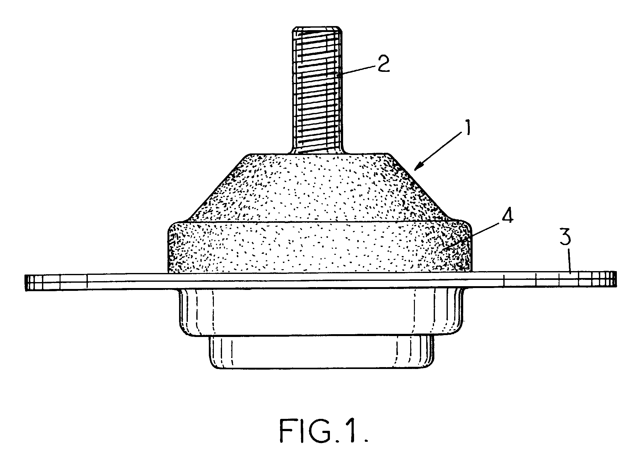
[0033] FIG. 1 shows an antivibration support 1 made using the method of the invention. The support comprises:

[0034] a metal pin 2 secured to a rigid metal base;

[0035] a rigid metal ring 3; and

[0036] an elastomer body 4 connecting the base of the pin 2 in leaktight manner to the ring 3, the elastomer being bonded to both pieces.

[0037] The base of the pin 2 and the ring 3 both constitute respective "metal inserts" 5 in the meaning of the invention. By way of example, the metal insert 5 is made of steel. The insert has a fixing surface 6 for bonding to the mass of elastomer constituting the body 4.

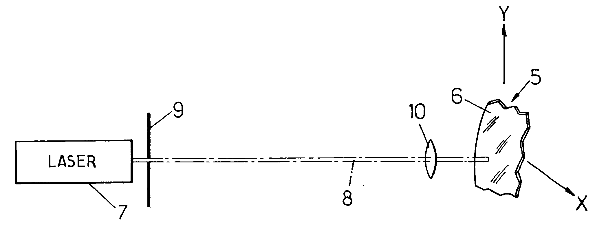
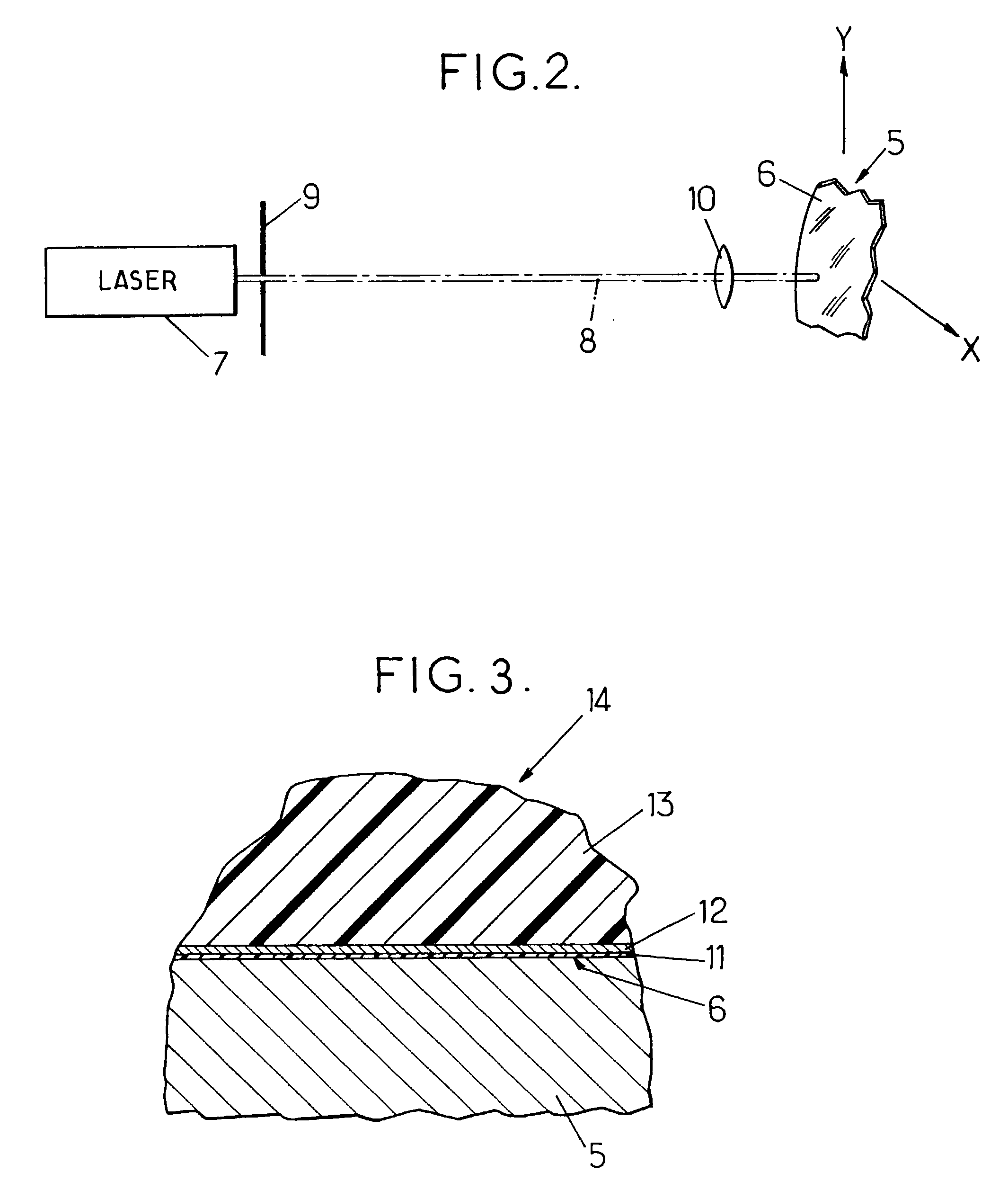
[0038] As shown in FIG. 2, prior to bonding, the fixing surface 6 is subjected to preliminary laser cleaning treatment, e.g. using a pulse laser 7 emitting a laser beam 8 which reaches the fixing surface 6 for cleaning by passing through a mask 9 and one or more lenses 10, for exampl...


PUM

PropertyMeasurementUnit
repetition frequencyaaaaaaaaaa
moldingaaaaaaaaaa
poweraaaaaaaaaa

Abstract

A method of manufacturing an antivibration device for motor vehicles, the device comprising at least one metal insert having at least one fixing surface bonded to an elastomer, the method including a cleaning step during which the fixing surface is scanned with a laser beam that is sufficiently powerful to eliminate the impurities present on said surface.

Description

[0001] The present invention relates to methods of manufacturing an antivibration device for motor vehicles, the device comprising at least one metal insert for bonding to an elastomer.[0002] The term "metal insert" is used herein to mean any piece made of metal for bonding to elastomer, and regardless of whether or not the piece is for embedding in the elastomer.[0003] More particularly, the invention relates to a method of manufacturing an antivibration device for motor vehicles, the device comprising at least one metal insert itself having at least one fixing surface bonded to an elastomer (e.g. rubber), the method comprising the following steps:[0004] a step of cleaning the fixing surface;[0005] a coating step during which the fixing surface is covered in at least one layer of fixing material for making a bond between the insert and the elastomer, said material being based on rubber; and[0006] a step of molding the elastomer onto the insert.[0007] During the coating step it can ...

Claims


Application Information

Patent Timeline
Patent Type & Authority Applications(United States)
IPC IPC(8): B08B7/00B29C70/68
CPCB29C70/683B08B7/0042
Inventor GIRARD, ANDREZARIFE, VICTOR
Owner HUTCHINSON SA
Why Eureka
Try Eureka