Optical retiming of an optical data signal

a technology of optical data signal and optical retimer, which is applied in the field of optical retimer, can solve the problems of optical data signal degrade, eye closure, and eye deformation

Active Publication Date: 2003-04-24
AVAGO TECH INT SALES PTE LTD
View PDF4 Cites 8 Cited by
  • Summary
  • Abstract
  • Description
  • Claims
  • Application Information

AI Technical Summary

Benefits of technology

0006] The present invention provides an optical retimer that retimes an optical data signal entirely in the optical domain, thus eliminating the need for optical-to-electrical and electrical-to-optical converters, which are needed to perform retiming in the electrical domain. The optical retimer samples the optical data signal during a clock cycle that has been determined by clock recovery, allows the sampled signal to travers

Problems solved by technology

As the optical data signal travels over a significant distance of the optical fiber, and passes through multiple optical-electrical-optical regeneration stages, the integrity of the optical data signal can degrade, thereby causing the "eye" to close.
The eye can be closed due to either loss of signal integrity in the horizontal direction caused by jitter in the rising and falling edges of the bit, or due to loss of integrity in the vertical

Method used


Image

  • Optical retiming of an optical data signal
  • Optical retiming of an optical data signal
  • Optical retiming of an optical data signal

Examples


Embodiment Construction

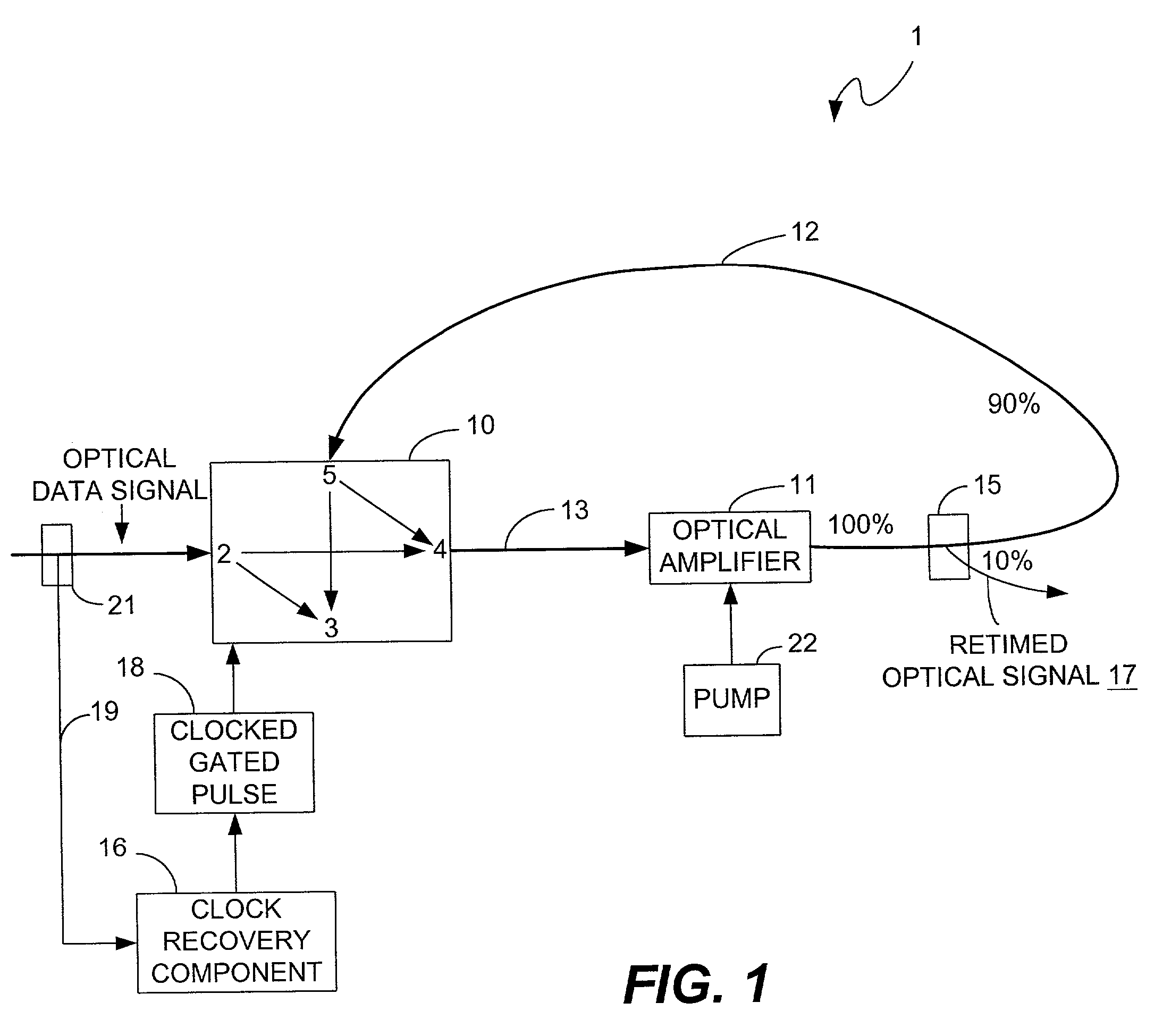
[0015] FIG. 1 is a block diagram that illustrates an example embodiment of the optical retimer 1 of the present invention for optically retiming an optical data signal. The present invention comprises an optical switching device 10, which is shown in FIG. 1 for example purposes as a 2.times.2 optical crossbar switch. An optical amplifier 11, which is powered by a pump 22, provides the gain in the ring configuration, which is represented by the arrows 12 and 13 and by the light path through the switching device 10 and the optical amplifier 11. The circumference of the ring, in terms of the amount of time that is required for light to circumnavigate, the ring is equal to the sampling aperture. In other words, the amount of time that is required for light to propagate through the optical switching device 10, over the portion of the ring represented by arrow 13, through the optical amplifier 11, and around the portion of the ring represented by arrow 12, is equal to the sampling apertur...


PUM


Abstract

An optical retimer is provided that retimes an optical data signal entirely in the optical domain, thus eliminating the need for optical-to-electrical and electrical-to-optical converters, which are needed to perform retiming in the electrical domain. Eliminating these conversion steps also eliminates, or at least decreases, the potential for errors in the retimed optical signal, such as jitter. The optical retimer samples the optical data signal during a clock cycle that has been determined by clock recovery, allows the sampled signal to traverse an optical pathway for the remainder of the cycle, out-couples a fraction of the sampled optical signal each time the signal traverses the optical pathway, and amplifies the signal traversing the pathway to maintain the signal at the power level it had when it was sampled. By the end of the clock cycle, the out-coupled signal corresponds to a retimed version of the original signal, synchronized to the recovered clock signal.

Description

[0001] The present invention relates to optically retiming an optical data signal, and an optical retimer for performing the retiming. One of the advantages of using the optical retimer of the present invention for performing retiming of an optical data signal is that it improves the integrity of the retimed optical signal relative to prior art techniques that convert the optical signal from the optical domain to the electrical domain, perform retiming in the electrical domain, and then re-convert the electrical signal to a retimed optical signal. In other words, the present invention eliminates, or at least decreases, the potential for errors (e.g., jitter) existing in the retimed optical signal. This is particularly important at high data rates, greater than a few billion bits per second, for example, where retiming in the electrical domain is severely limited by the speed of today's integrated circuit processes.[0002] In optical fiber communications links, an optical source, typi...

Claims


Application Information

Patent Timeline
IPC IPC(8): H04B10/299H04L7/00
CPCH04L7/0075H04B10/299
Inventor LEMOFF, BRIAN E.NISHIMURA, KEN A.
Owner AVAGO TECH INT SALES PTE LTD
Why Eureka
Try Eureka