

Antireflection coating and optical element using the same
a technology of anti-reflection coating and optical element, applied in the direction of optical elements, water-setting substance layered products, instruments, etc., can solve the problems of increasing the number of coating layers, limiting the number of thin film coating materials capable of being used on a practical basis, and narrow limits of refractivity applicable in the coating structur
- Summary
- Abstract
- Description
- Claims
- Application Information
AI Technical Summary
Problems solved by technology
Method used
Image

Examples
embodiment 1
[0083] (Embodiment 1)
[0084] Embodiment 1 in the present invention will be described with reference to the drawings.
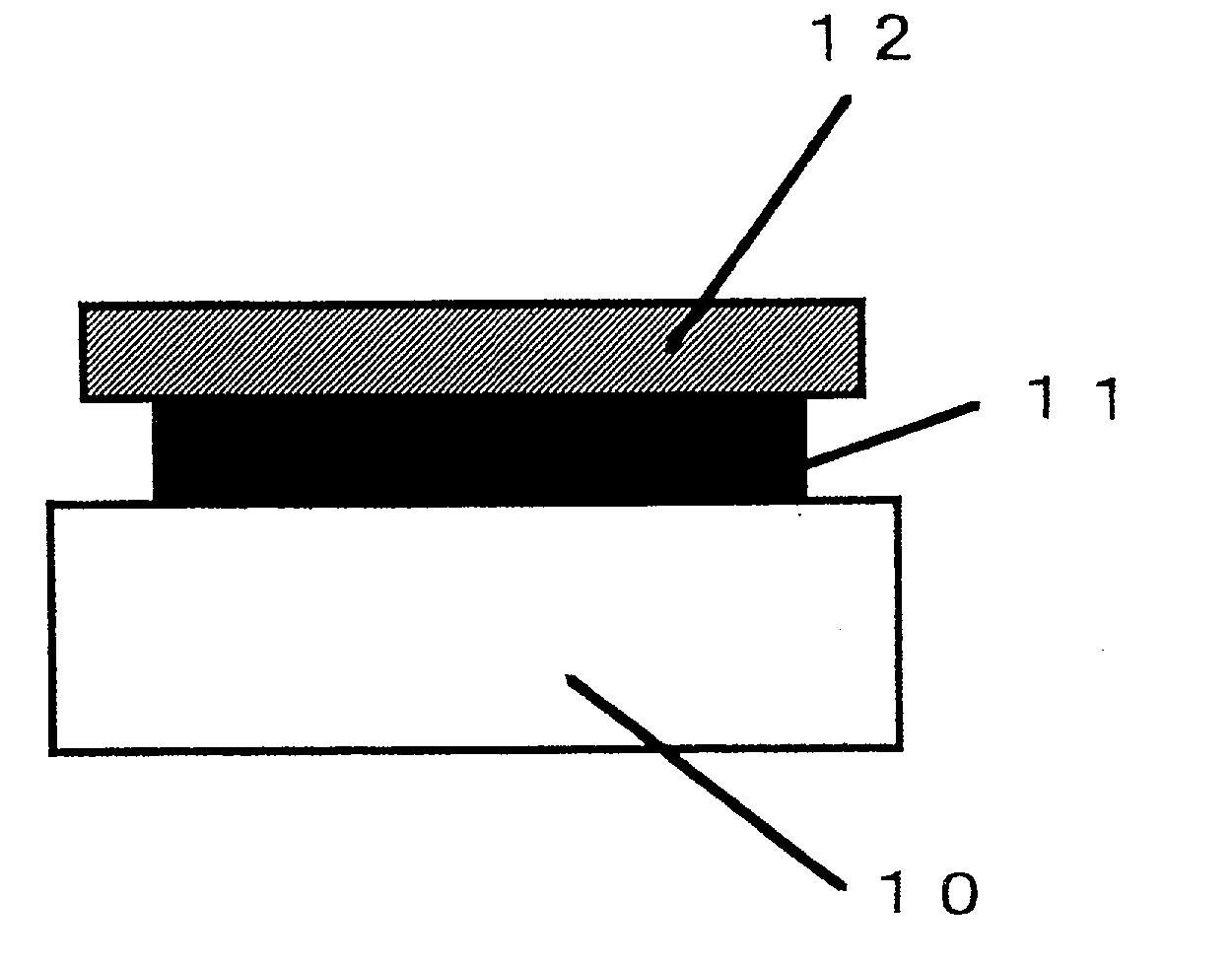
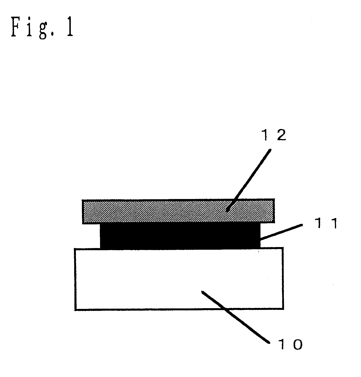
[0085] FIG. 1 is a sectional view of an antireflection coating provided on the surface of a lens 10 corresponding to a substantially transparent substrate with refractivity of h.sub.0 of the present invention. The coating structure is very simple, and the productivity is enhanced.
[0086] BK7 (with wavelength of 1510 nm and refractivity of 1.50) is used as a base material for the lens 10, and is provided thereon with a multi-layer coating constituted by a first layer 11 and second layer 12 shown in Table 1.
1TABLE 1 Optical thickness Constitution Materials Refractivity Thickness (nm) (nm) Second layer 12 SiO.sub.2 1.44 183 264 First layer 11 TiO.sub.2 2.20 292 642 Lens 10 BK7 1.50 -- --
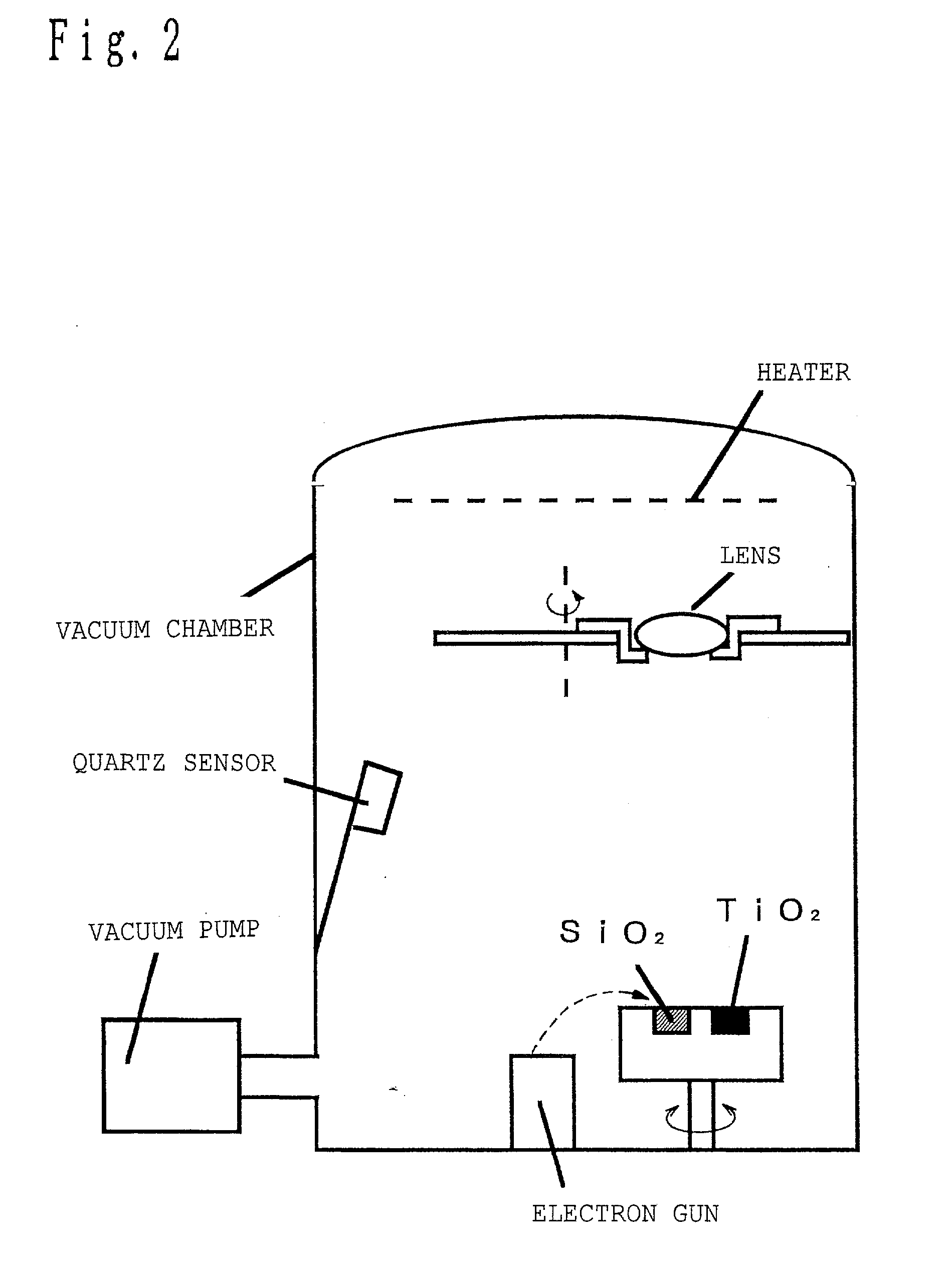
[0087] One example of methods for forming the multi-layer coating shown in Table 1 will be described below.
[0088] The coating is formed using a vacuum coater as shown in FIG. 2.
[0089] After ...
embodiment 2
[0104] (Embodiment 2)
[0105] Embodiment 2 in the present invention will be described with reference to the drawings.
[0106] FIG. 4 is a sectional view of an antireflection coating provided on the surface of a lens corresponding to a substantially transparent substrate with refractivity of h.sub.0 of the present invention 40. The coating has a very simple structure, and the productivity enhanced.
[0107] BK7 (with refractivity of 1.50) is used as abase material for the lens 40, and is provided thereon with a multi-layer coating constituted by a first layer 41 and second layer 42 shown in Table 3.
3TABLE 3 Optical thickness Constitution Materials Refractivity Thickness (nm) (nm) Second layer 42 MgF.sub.2 1.37 196 268 First layer 41 TiO.sub.2 2.20 302 665 Lens 40 BK7 1.50 -- --
[0108] The method for forming the multi-layer coating of Table 3 is not described here because it is almost same as the method described in Embodiment 1.
[0109] FIG. 5 shows dependency of reflectance on wavelengths whe...
embodiment 3
[0122] (Embodiment 3)
[0123] Embodiment 3 in the present invention will be described with reference to the drawings.
[0124] FIG. 6 is a sectional view of an antireflection coating provided on the surface of a lens 60 corresponding to a substantially transparent substrate with refractivity of h.sub.0 of the present invention. The coating has a very simple structure, and the productivity is enhanced.
[0125] BK7 (with refractivity of 1.50) is used as abase material for the lens 60, and is provided thereon with a multi-layer coating constituted by a first layer 61, second layer 62 and third layer 63 shown in Table 5.
5TABLE 5 Optical thickness Constitution Materials Refractivity Thickness (nm) (nm) Third layer 63 SiO.sub.2 1.44 182 261 Second layer 62 TiO.sub.2 2.20 295 649 First layer 61 SiO.sub.2 1.44 63 91 Lens 60 BK7 1.50 -- --
[0126] The method for forming the multi-layer coating of Table 5 is not described here because it is almost same as the method described in Embodiment 1.
[0127] FI...
PUM
| Property | Measurement | Unit |
|---|---|---|
| Fraction | aaaaa | aaaaa |
| Fraction | aaaaa | aaaaa |
| Fraction | aaaaa | aaaaa |
Abstract
Description
Claims
Application Information