

Power source unit
a power source and power converter technology, applied in the direction of hybrid vehicles, electric generator control, instruments, etc., can solve the problems of dc-dc converter 106, cost increase, cost increase,
- Summary
- Abstract
- Description
- Claims
- Application Information
AI Technical Summary
Benefits of technology
Problems solved by technology
Method used
Image

Examples
first embodiment
[0021] First Embodiment
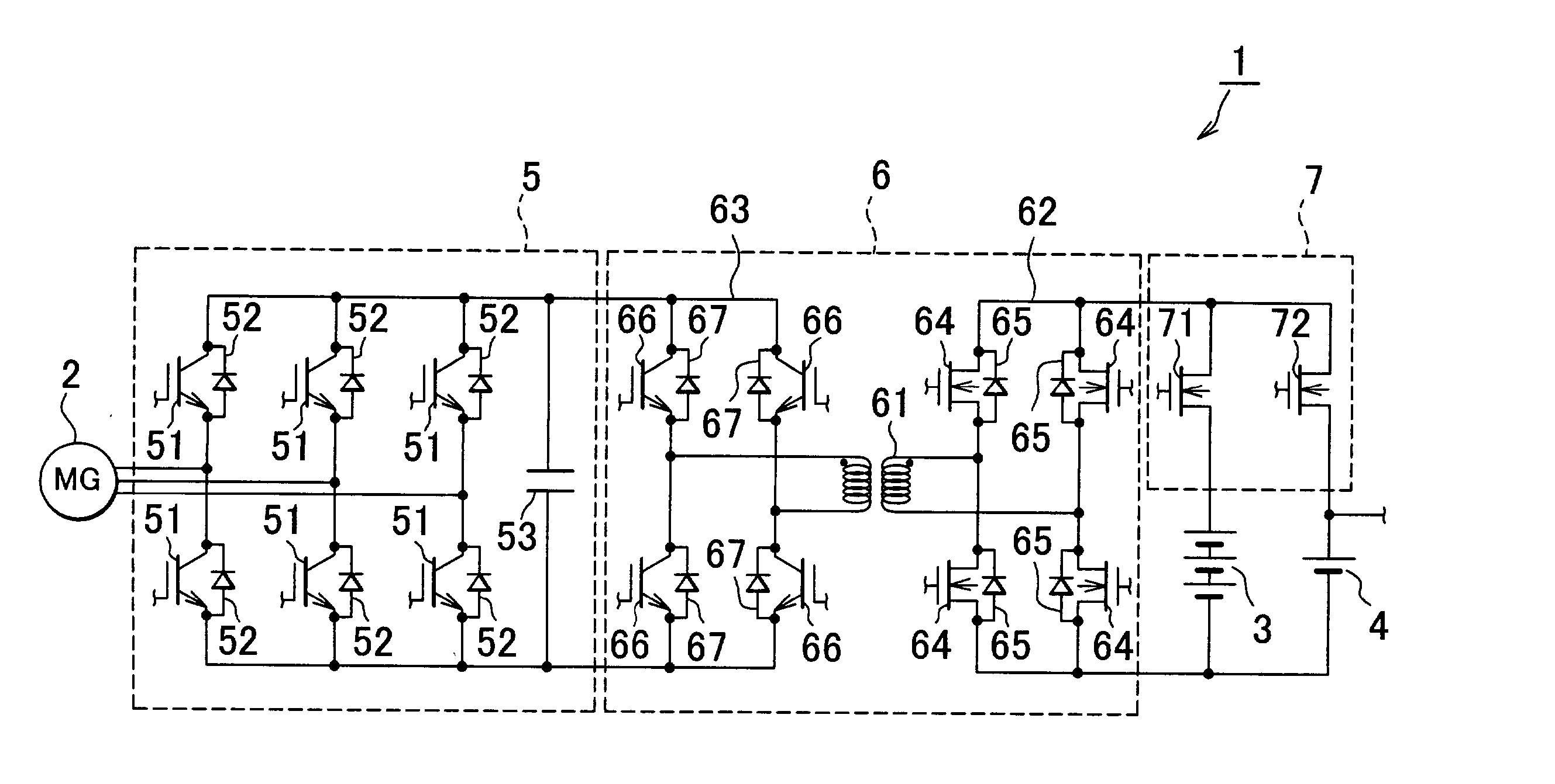
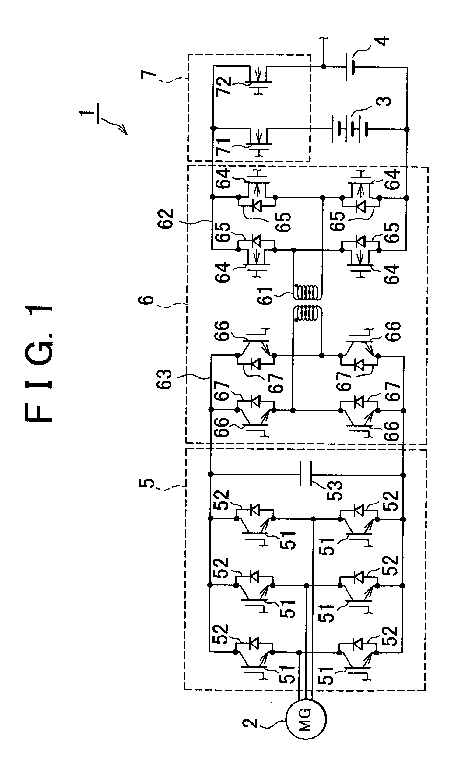
[0022] FIG. 1 is an exemplary schematic view of a power source unit of a first embodiment. As shown in FIG. 1, a power source unit 1 is mounted on a hybrid vehicle having a combination of an engine and a motor generator 2. The power source unit 1 can be mounted on any type of the hybrid vehicle including a series type in which wheels are driven by a motor generator, and an engine serves to supply power to the motor generator 2, a parallel type in which wheels can be driven by both an engine and a motor generator, or a parallel series type in which functions of both the series type and the parallel type can be obtained.
[0023] The power source unit 1 has a main battery 3 and an accessory battery 4. The main battery 3, as the chargeable / dischargeable secondary battery, mainly serves to supply electricity to the motor generator 2. The main battery 3 is of a higher voltage type, DC 36 to 40 V, for example, compared with the accessory battery 4. The accessory batter...
second embodiment
[0046] Second Embodiment
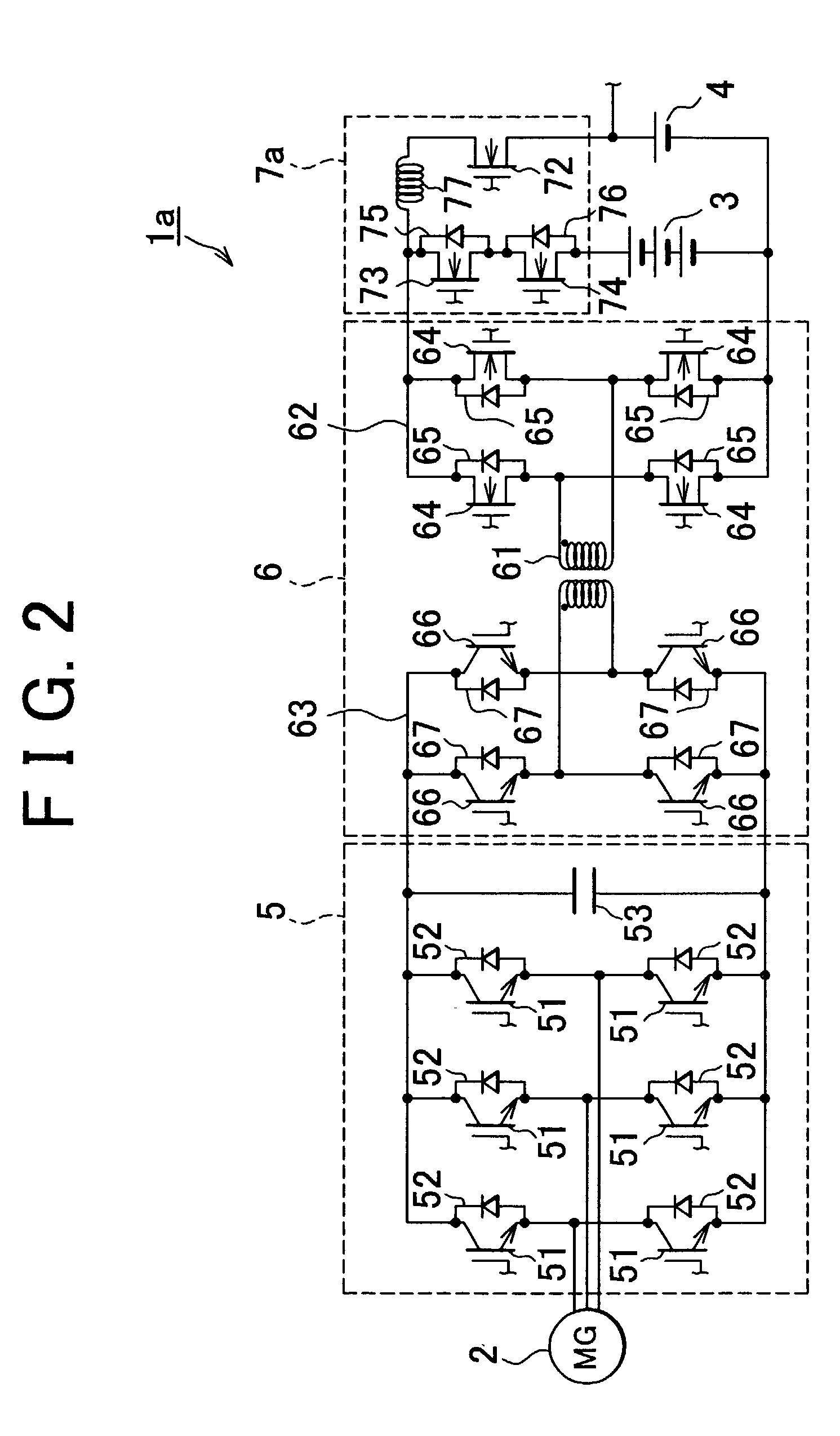
[0047] FIG. 2 is an exemplary schematic view of a power source unit according to a second embodiment. As shown in FIG. 2, a power source unit 1a has a similar configuration as that of the power source unit 1 of the first exemplary embodiment. That is, the power source unit 1a has a main battery 3, accessory battery 4, inverter 5, and power converting circuit 6. Like the switching circuit 7 of the first embodiment, a switching circuit 7a of the power source unit 1a serves to switch the connection between the power converting circuit 6 and the main battery 3 and the power converting circuit 6 and the accessory battery 4. The switching circuit 7a and the second bridge circuit 62 constitute the step-up chopper so as to allow power transfer between the main battery 3 and the accessory battery 4.
[0048] In the switching circuit 7a, a transistor 73 and a transistor 74 are connected in series between the first bridge circuit 62 and the main battery 3. A coil 77 and th...
first exemplary embodiment
[0062] As described above, according to the power source unit 1a relating to this embodiment (in addition to the same operation effects as in the power source unit 1 relating to the first exemplary embodiment) by connecting the coil 77 between the main battery 3 and the auxiliary battery 4 via the switching circuit 7a, it is possible to cause the power converting circuit 6 and the switching circuit 7a to function as step-up and step-down choppers. Therefore, without placing a step-up circuit other than the power converting circuit 6 and the switching circuit 7a, power transfer between the main battery 3 and the auxiliary battery 4 is enabled.
[0063] Although a power source unit mounted in a vehicle is explained in the aforementioned embodiments, the power source unit relating to the invention may be adapted to a unit other than one mounted in a vehicle.
[0064] As explained above, according to the invention, as a result of enabling a switch of connection between the power converting me...
PUM
 Abstract
Description
Claims
Application Information