

Combustion chamber and method for operating said combustion chamber
a combustion chamber and combustion chamber technology, applied in combustion types, lighting and heating apparatus, turbine/propulsion engine ignition, etc., can solve the problems of relatively difficult to cool the surface of the fuel lance in the hot gas flow, relatively large gap between the burner wall and the fuel lance, and relatively difficult to seal
- Summary
- Abstract
- Description
- Claims
- Application Information
AI Technical Summary
Benefits of technology
Problems solved by technology
Method used
Image

Examples
Embodiment Construction
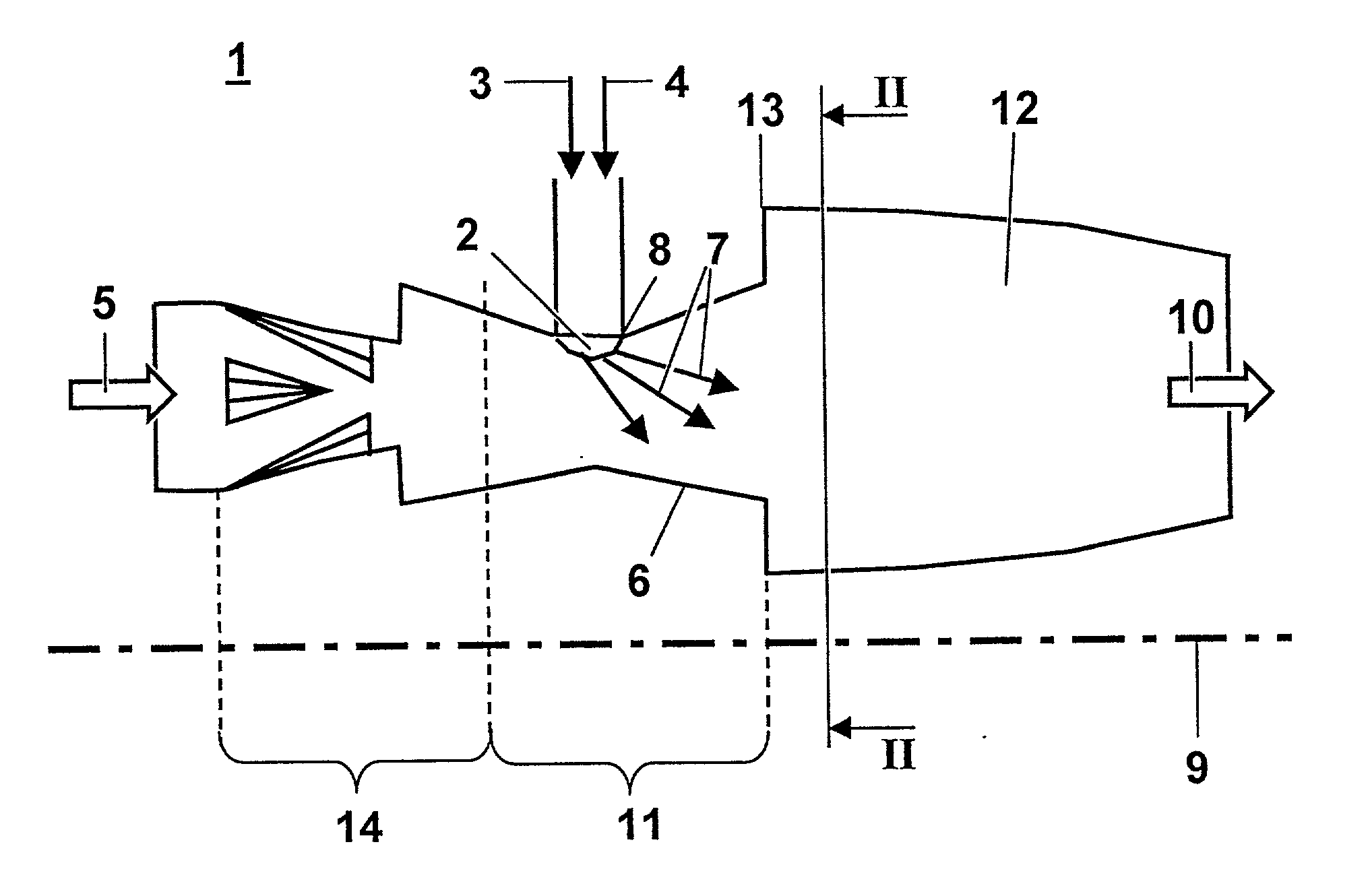
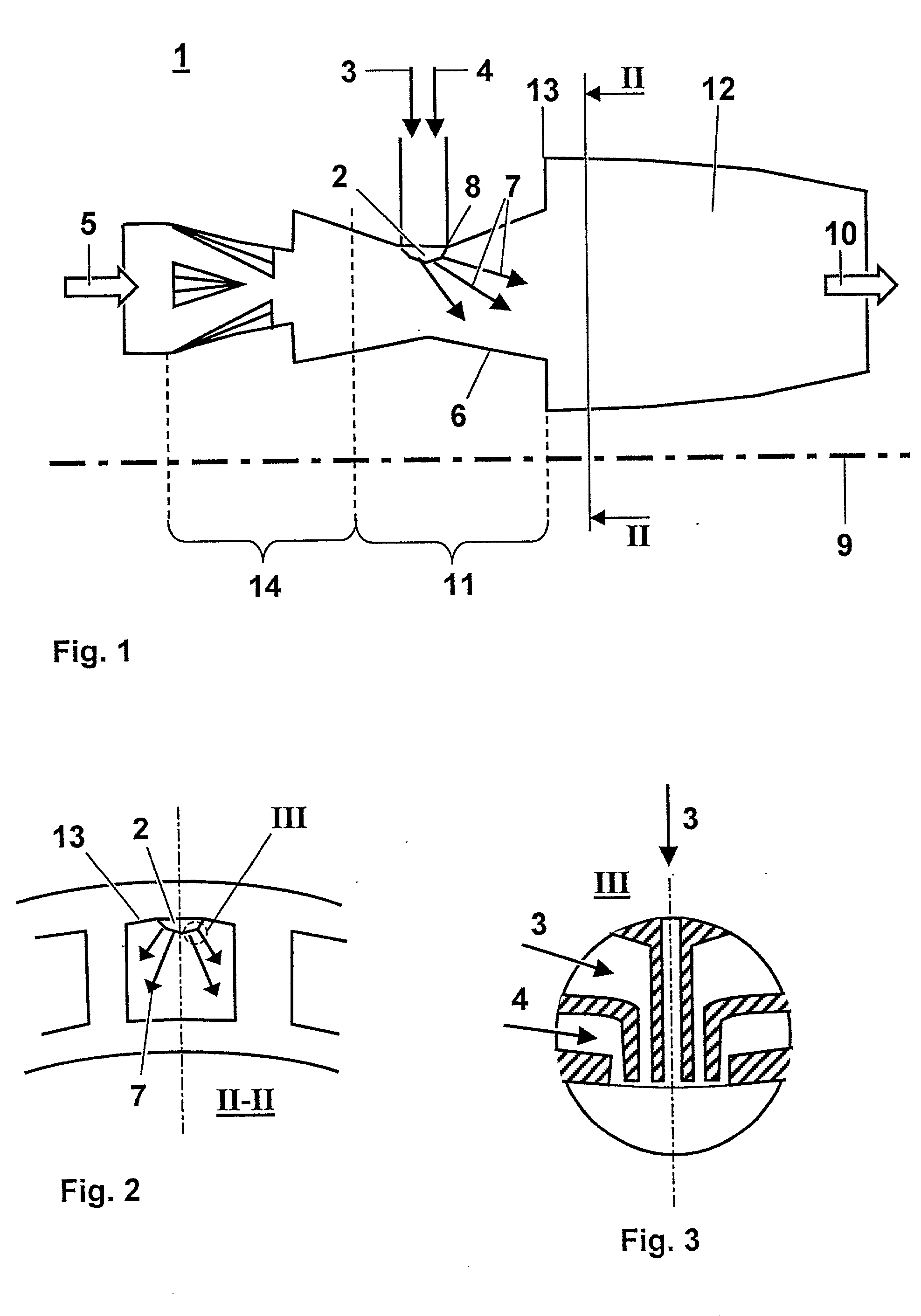
[0004] It is the objective of the invention to avoid said advantages. The invention realizes the objective of creating a combustion chamber and a method for operating said combustion chamber that make it possible to minimize the interference with the hot gas flow in the mixing zone of the combustion chamber. This should be accomplished along with simultaneously less cooling of the fuel lance, and an improved behavior of the combustion chamber in all load ranges should be achieved.
[0005] According to the invention, this is achieved with a method according to the preamble of claim 1 in that the fuel is injected from at least one side wall of the mixing zone of the combustion chamber; and in the combustion chamber according to the invention to the preamble of claim 4, this is achieved in that the at least one fuel lance is set into a side wall of the mixing zone of the combustion chamber. Naturally, it would also be conceivable that support air is also injected through this fuel lance....
PUM
 Abstract
Description
Claims
Application Information