

Inspection method and device for detecting defect
Inactive Publication Date: 2003-06-19
NGK INSULATORS LTD
View PDF2 Cites 38 Cited by
- Summary
- Abstract
- Description
- Claims
- Application Information
AI Technical Summary
Benefits of technology
[0013] In the inspection method according to the present invention, to easily identify the location of a defect, it is preferable that the light is planarly emitted to detect a defect in a two-dimensional fashion. Furthermore, to easily record the location of detection, it is preferable that an image of the visualized and detected particulate is recorded by a camera. In addition, from the viewpoint of detection sensitivity and easier post-treatment, a particle diameter of the particulate generated is preferably 0.3 to 200 .mu.m, and more preferably 0.5 to 50 .mu.m, and still more preferably 1 to 10 .mu.m. The inspection method for detecting a defect in accordance with the present invention can be preferably used when a test object is a porous member, and also preferably used when the test object is a honeycomb structure, especially a diesel particulate filter. In this case, from the aspect of detection sensitivity, the light is emitted such that it passes in the vicinity of a surface from which the particulate discharged and substantially in parallel to the surface from which the particulate is discharged.
[0015] To allow the location of detection to be easily identified, the light emitting means of the inspection apparatus for detecting a defect in accordance with the present invention is preferably a means for planarly emitting the light. Furthermore, to allow the location of a defect to be easily recorded, the inspection apparatus for detecting a defect in accordance with the present invention preferably further comprises a recording means for recording an image of the particulate that has been visualized and detected. In addition, from the viewpoint of detection sensitivity and easier post-treatment, the particulate generating means of the apparatus for detecting a defect in accordance with the present invention is preferably a means for generating particulates having particle diameters of 0.3 to 200 .mu.m, more preferably 0.5 to 50 .mu.m, and still more preferably 1 to 10 .mu.m. The inspection apparatus for detecting a defect in accordance with the present invention is used for preferably a porous member, more preferably a honeycomb structure, and particularly a diesel particulate filter as a test object. In this case, from the aspect of detection sensitivity, the inspection apparatus for detecting a defect in accordance with the present invention preferably comprises the light emitting means for emitting light such that it passes substantially in parallel to a particulate discharge surface of the honeycomb structure from which the particulate is discharged.
[0025] An important characteristic of the inspection method in accordance with the present invention is to emit light with high directivity, to irradiate the particulates that are discharged through a defective portion of a test object, so as to visualize and detect the particulates. Irradiating particulates with the light permits detection of a defect with high sensitivity even if a test object has a shape that does not allow a defect to be checked from outside.
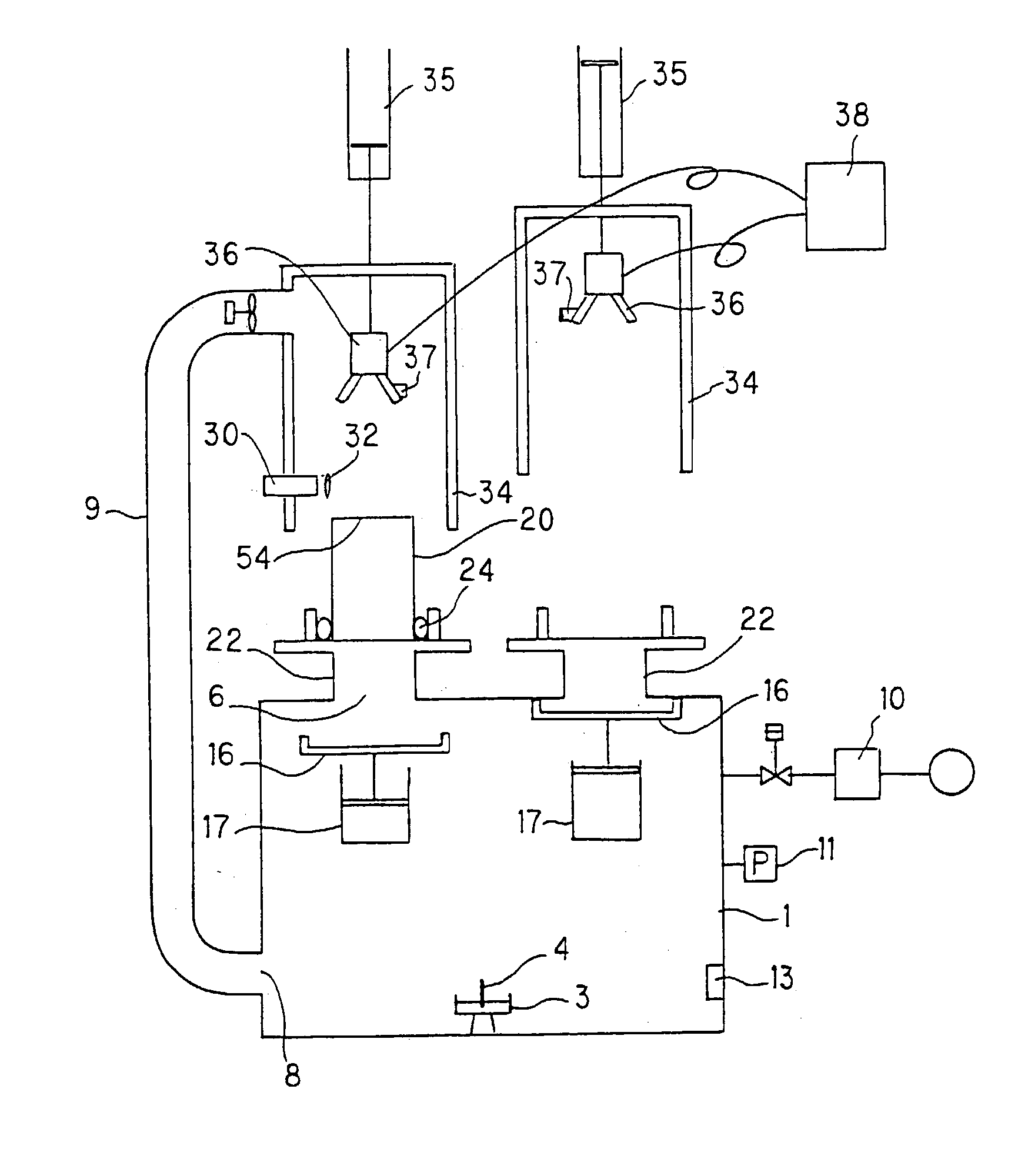
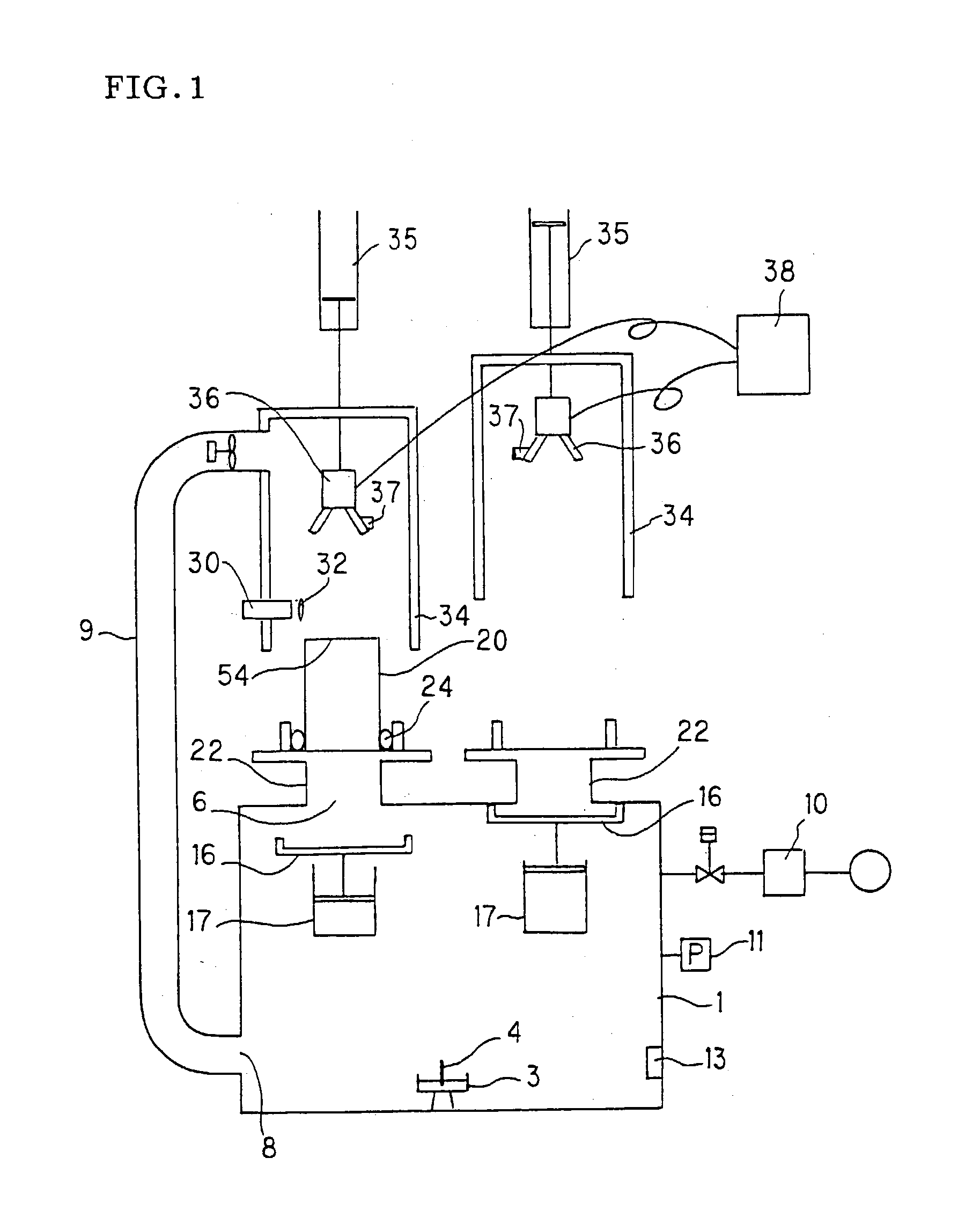
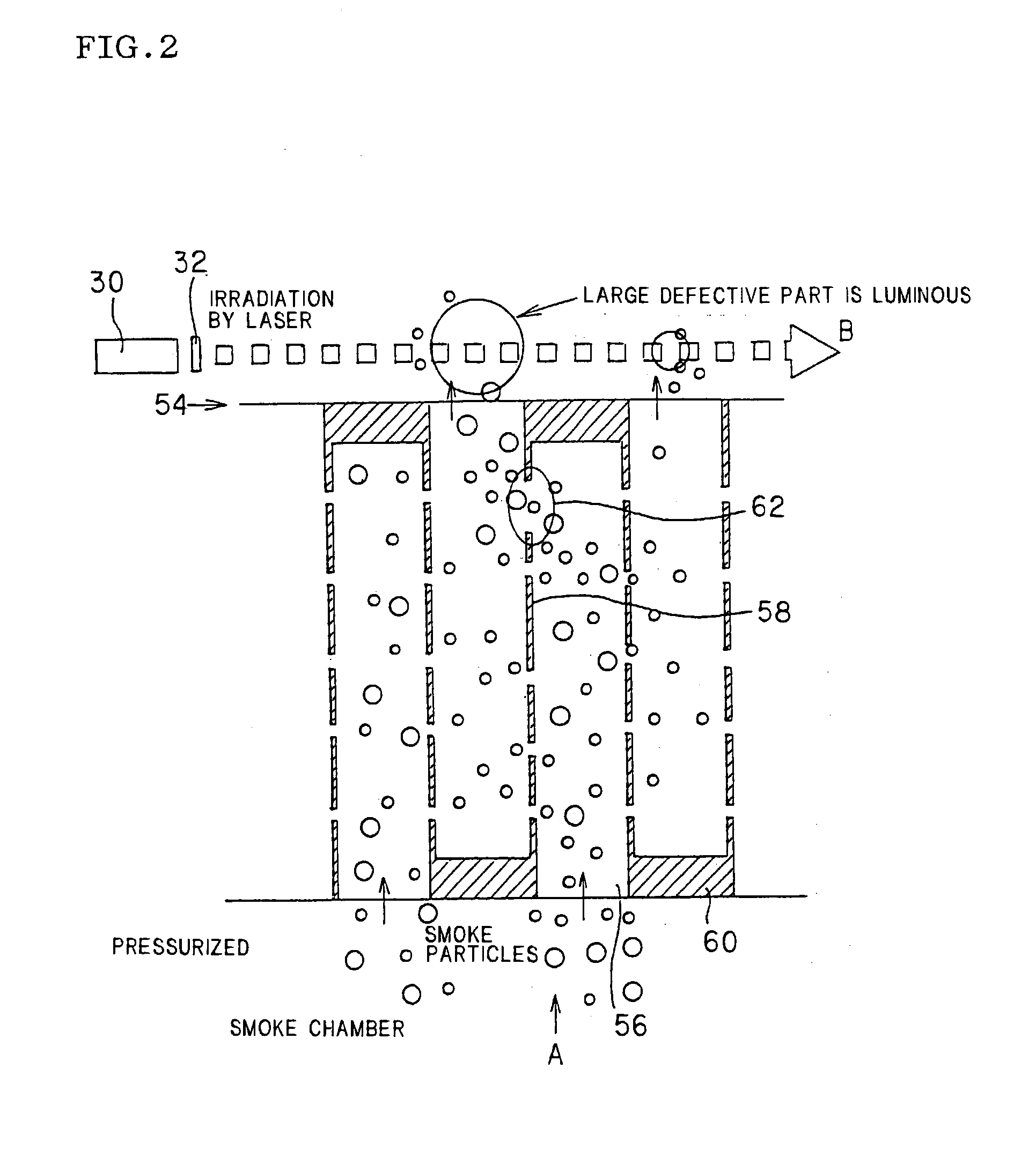
[0027] If the honeycomb structure shown in FIG. 2 is a porous member, particulates are introduced from a direction A into a passage 56 where a partition 58 has a defect 62. The introduced particulates pass through the defect 62 and are discharged from a particulate discharge surface 54. If light with high directivity passes in a direction B in the vicinity of the particulate discharge surface 54, then the discharged particulates irregularly reflect the light, making them visible. In this case, if a passage has a larger defect, then it allows larger and more particulates to be discharged through the passage and larger particulates irregularly reflect more light. Hence, a spot having a larger defect irregularly reflects more light, thus making it possible to detect a passage that has a defect. If a sealing portion 60 has a defect, then particulates having larger particle diameters or more particulates are discharged through the passages affected by the defect, so that the passage having the defective sealing portion can be detected also. If the test object is nonporous, e.g., if the honeycomb structure shown in FIG. 2 is a compact prior to firing, then the introduced particulates are discharged only through a passage that has a defect in the partition 58 or the sealing portion 60. The discharged particulates irregularly reflect light, making themselves visible. This makes it possible to detect a defective passage.
Problems solved by technology
Therefore, the presence of a hole, i.e., a defect, that pierces the film or wall of a porous member interferes with the filtering performance of the porous member or the performance as a catalyst carrier.
In the case of a nonporous member, a hole, that is, a defect, frequently prevents the performance expected of the material from being fully exhibited.
There are, however, some cases where the inspection is difficult, depending on the configuration, or the position or the size of a defect to be detected, of a test object, which may be a porous member or a nonporous member.
Hence, defects in the partitions of such a structure cannot be observed from outside.
However, since the method involves the use of a soot-like substance, the soot-like substance that adheres to a honeycomb structure must be removed by heat treatment after inspection, and a few hours are required for such post-treatment.
In addition, inspecting one test object requires 5 to 6 minutes.
Method used
View moreImage
Smart ImageViewing Examples

Examples
example 2 and 3
[0045] The inspections were carried out for the filters (b) and (c) in the same manner as that of Example 1. The time required from the start of the inspection to photographing was five seconds. The filtering functions remained intact even when post-treatment was not carried out after the inspection. The photographed images are shown in FIG. 6(b) and FIG. 6(c).
Login to View More PUM
| Property | Measurement | Unit |
|---|---|---|
| Particle diameter | aaaaa | aaaaa |
Abstract
An inspection method for detecting a defect in a test object. A particulate is generated, then the generated particulate is introduced into a test object. Subsequently, light having high directivity is emitted such that the light passes in the vicinity of the test object to irradiate the particulate discharged from the test object, thereby making the particulate visible. An inspection apparatus for detecting a defect in a test object, including a particulate generating means for generating a particulate, a particulate introducing means for introducing the particulate into a test object, and a light emitting means for emitting light with high directivity that passes in the vicinity of the test object and irradiates the particulate discharged from the test object thereby to visualize the particulate. The inspection method and apparatus detect a defect of a test object with high sensitivity, permit easier identification and recording of the location of a defect, and shorten an inspection time and the time required for the pre-treatment and post-treatment before and after an inspection, or obviate the need for the pre-treatment and post-treatment.
Description
[0001] The present invention relates to an inspection method and an inspection apparatus for detecting a defect of a test object and, more particularly, to an inspection method and an inspection apparatus for detecting a defect of a test object that allow a defect to be detected with high sensitivity and permit quick inspection and post-processing.[0002] Test objects requiring inspection for detecting defects include, for example, porous members. Porous members are extensively used for filters or catalyst carriers, etc. Porous members are used, for instance, for the exhaust gas purifiers of heat engines, such as internal combustion engines, or combustion equipment, such as boilers, for reformers of liquid fuel or gas fuel, and for purifying facilities of water supply and sewerage. Furthermore, honeycomb-shaped porous members are used for diesel particulate filters or hot gas dust collectors to capture and remove particulate substances contained in a dust containing fluid, such as ex...
Claims
Login to View More Application Information
Patent Timeline
 IPC IPC(8): B01D46/00B01D46/44G01N15/08B01D65/10F01N3/00F01N3/02G01M3/20G01M3/38G01N21/88G01N21/95
CPCB01D46/0086B01D46/442B01D65/102B01D65/104B01D2273/18G01N21/95692G01M3/38G01N15/0826G01N21/88G01N21/95G01M3/20
InventorENOMOTO, AKIOMIYASHITA, KOUICHI
OwnerNGK INSULATORS LTD