Deployment device, system and method for medical implantation

a technology of medical implantation and deployment device, applied in the direction of blood flow measurement, catheter, sensor, etc., can solve problems such as difficult tasks

Inactive Publication Date: 2003-07-03
REMON MEDICAL TECH
View PDF0 Cites 397 Cited by
  • Summary
  • Abstract
  • Description
  • Claims
  • Application Information

AI Technical Summary

Benefits of technology

0007] Hence, an object of the present invention is to provide a deployment device and system, and also a deployment method, having advantages in the above respects for deploying a medical implant at a target location in a body cavity, such as a blood vessel or other body lumen, bladder and the like.

Problems solved by technology

These tasks become difficult when self-expansible implants inherently having a spring like action when let expand are to be precisely deployed at a target location.

Method used


Image

  • Deployment device, system and method for medical implantation
  • Deployment device, system and method for medical implantation
  • Deployment device, system and method for medical implantation

Examples


Embodiment Construction

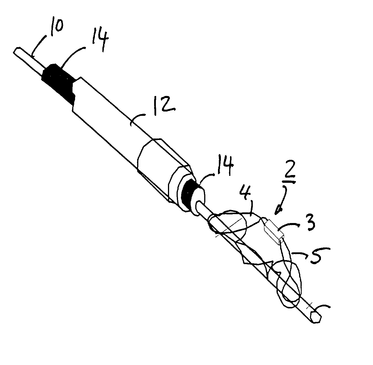
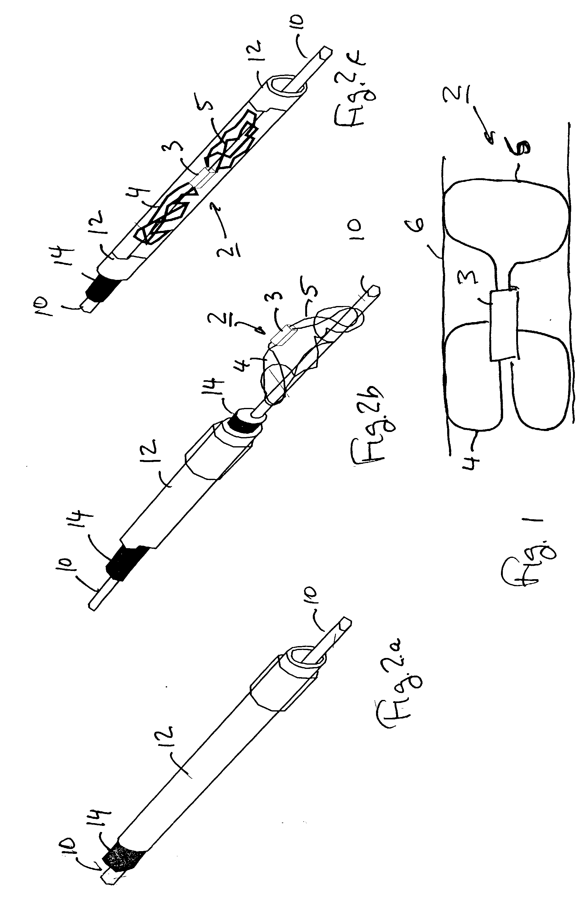
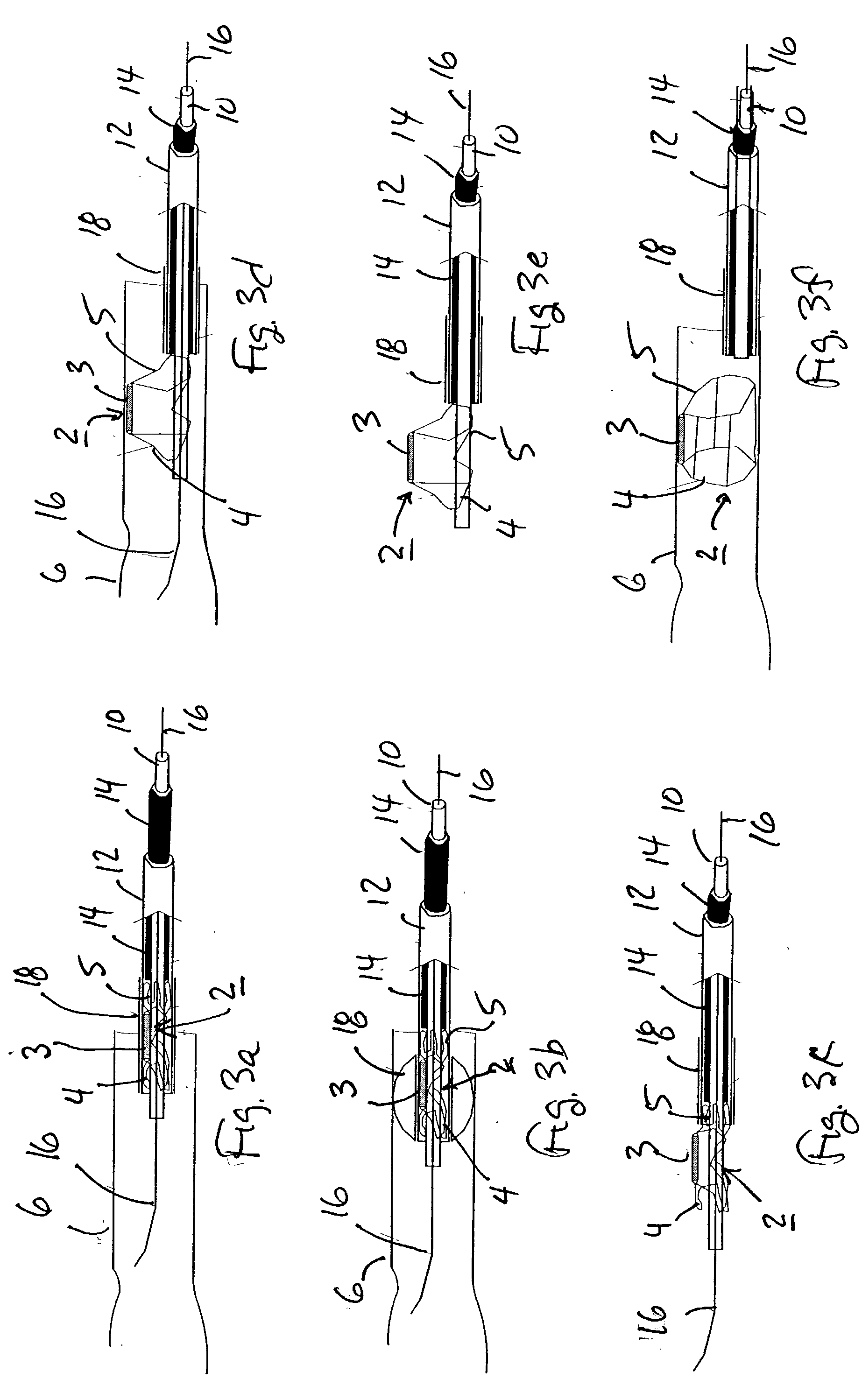
[0032] The present invention is of a deployment device for deploying a self-expansible medical implant, at a target location in a body cavity. While generally, the expansion of self-expansible structures tends to be abrupt, and the impact of expansion may cause injury, a two-stage expansion process of the present invention minimizes the impact of exapnsion. Additionally, an ability to manuever the medical imlant into position, after the first stage of expansion, provides for accurate positioning.

[0033] Thus the present invention is of a deployment device for precise and well-controlled manner of deployment, so as to minimize damage to the cavity wall and to position the implant accurately at the target location.

[0034] The implant may be, for example, a stent, a filter, a sensor (e.g., pressure, flow-rate, temperature, oxygen concentration) a septal occluder, a coil, a detachable coil for aneurysm treatment, a graft, a deflector, or any other device for performing or measuring a phys...


PUM


Abstract

A deployment device for deploying a self-expansible medical implant at a target location in a body cavity, is provided. While generally, the expansion of self-expansible structures tends to be abrupt, and the impact of expansion may cause injury, a two-stage expansion process of the present invention minimizes the impact of exapnsion. Additionally, an ability to manuever the medical imlant into position, after the first stage of expansion, provides for accurate positioning. Thus the present invention is of a deployment device for precise and well-controlled manner of deployment, so as to minimize damage to the cavity wall and to position the implant accurately at the target location. The deployment device includes: an inner tube; an outer tube; and an implant received on the inner tube and enclosed by the outer tube. The implant has a self-expansible anchoring element which is in a contracted condition when enclosed by the outer tube, expands to a partially-expanded condition when the outer tube is retracted, and expands to a fully-expanded condition when the inner tube is removed.. The implant is deployed by introducing the deployment device to the target location in the body cavity; retracting the outer tube with respect to the implant such that the anchoring element self-expands from its contracted condition to its partially-expanded condition; and withdrawing the inner tube from the implant such that the anchoring element self-expands from its partially-expanded condition to its fully-expanded condition to firmly fix the implant at the target location within the body cavity.

Description

FIELD AND BACKGROUND OF THE INVENTION[0001] The present invention relates to a deployment device, system and method for deploying a medical implant at a target location in a body cavity.[0002] For various purposes, it is often desired or necessary to implant permanently or for a limited time period, a medical device (referred to herein as implant) in a body cavity. Examples of various types of medical devices which are presently implanted include stents, deflectors, filters, sensors, septal occluders, coils for aneurysm and the like. The implant is in a contracted condition when delivered to the target location in the cavity, e.g., a blood vessel or other lumen, and is expanded at the target location in order to fix it in place.[0003] Often implants are delivered to their intrabody position via an endoluminal procedure, by the use of a catheter based delivery and deployment device navigated into the target cavity aided by a guide-wire which is prepositioned in the body lumen. The ca...

Claims


Application Information

Patent Timeline
Patent Type & Authority Applications(United States)
IPC IPC(8): A61B5/00A61B5/0215A61B5/029A61B5/053A61B17/00A61B17/12A61F2/01A61F2/02A61F2/82A61N1/05
CPCA61B5/0215A61N2001/0585A61B5/053A61B5/145A61B5/413A61B5/6862A61B5/6876A61B5/6882A61B5/6886A61B17/1214A61B17/12168A61B2017/00022A61B2017/00026A61B2017/00084A61B2017/00575A61B2017/1205A61F2/01A61F2/82A61F2/95A61F2250/0001A61N1/05A61N1/057A61B5/029
Inventor FASTOVSKY, VITALYYARDEN, ORITBURSTEIN, YEHIELROZENMAN, YOSEPH
Owner REMON MEDICAL TECH
Why Eureka
Try Eureka