Control apparatus, control method , and engine control unit

a control apparatus and control method technology, applied in the direction of electric controllers, electric control, instruments, etc., can solve the problems of control system stability loss, control accuracy drop, air/fuel ratio control experience lower stability and controllability, etc., to improve the characteristic of post-catalyst exhaust gas and improve accuracy

Inactive Publication Date: 2003-07-03
HONDA MOTOR CO LTD
View PDF11 Cites 35 Cited by
  • Summary
  • Abstract
  • Description
  • Claims
  • Application Information

AI Technical Summary

Benefits of technology

[0007] The present invention has been made to solve the foregoing problem, and it is an object of the invention to provide a control apparatus, a control method, and an engine control unit which are capable of eliminating a slippage in control timing between the input and output of a controlled object, even when the controlled object exhibits a relatively large dynamic characteristic such as a phase delay, a dead time, and the like, and of capable of improving the stability and controllability of control.

Problems solved by technology

According to the conventional control apparatus mentioned above, when a dynamic characteristic of a controlled object has a relatively large phase delay, a dead time, or the like, this causes a delay in outputting an output signal, which reflects an input signal from the controlled object, after the controlled object is fed with the input signal, leading to a slippage in control timing between the input and output of the controlled object.
As a result, a control system could lose the stability.
For example, when an internal combustion engine is controlled for an air / fuel ratio of exhaust gases using a fuel injection amount of the internal combustion engine as an input, a time lag is needed until the air / fuel ratio of the exhaust gases actually change after a fuel has been actually injected, so that the air / fuel ratio control experiences lower stability and controllability, resulting in an instable characteristic of exhaust gases purified by a catalyst.

Method used


Image

  • Control apparatus, control method , and engine control unit
  • Control apparatus, control method , and engine control unit
  • Control apparatus, control method , and engine control unit

Examples


Embodiment Construction

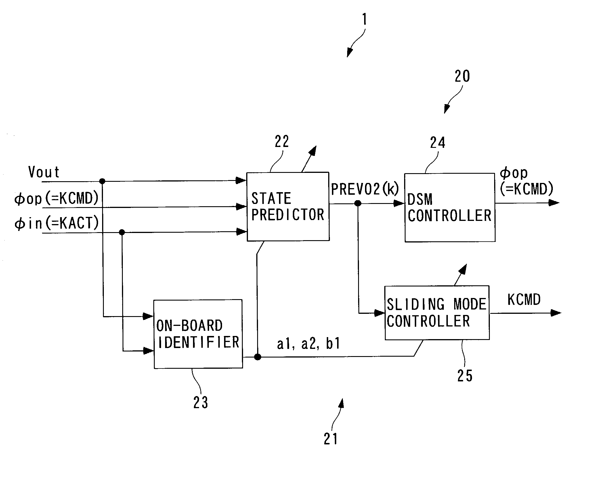
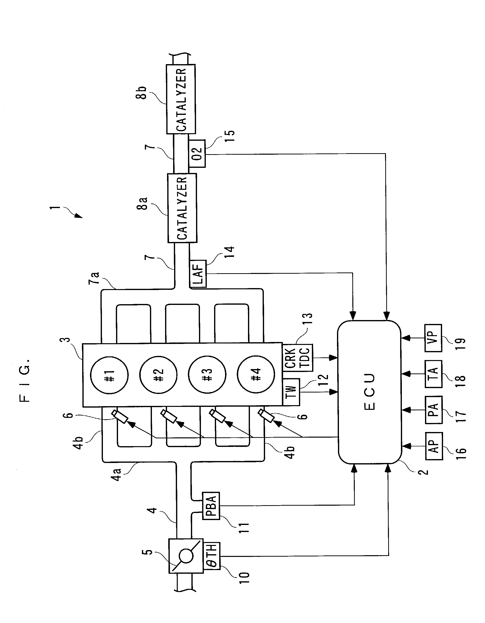
[0429] In the following, a control apparatus according to a first embodiment of the present invention will be described with reference to the accompanying drawings. The control apparatus according to the first embodiment is configured to control, by way of example, an air / fuel ratio of an internal combustion engine. FIG. 1 generally illustrates the configuration of the control apparatus 1 and an internal combustion engine (hereinafter called the "engine") 3 which applies the control apparatus 1. As illustrated, the control apparatus 1 comprises an electronic control unit (ECU) 2 which controls the air / fuel ratio of an air / fuel mixture supplied to the engine 3 in accordance with an operating condition thereof.

[0430] The engine is an in-line four-cylinder gasoline engine equipped in a vehicle, not shown, and has four, a first to a fourth cylinder #1-#4. A throttle valve opening sensor 10, for example, comprised of a potentiometer or the like, is provided near a throttle valve 5 in an ...


PUM


Abstract

A control apparatus is provided for eliminating a slippage in control timing between the input / output of a controlled object, even when the control object exhibits a relatively large dynamic characteristic such as a phase delay, a dead time, or the like, to improve the stability and the controllability of the control. The control apparatus comprises a state predictor for calculating a predicted value of a value indicative of an output of a controlled object based on a prediction algorithm, and a DSM controller for calculating a control input to the controlled object based on one modulation algorithm selected from a DELTA modulation algorithm, a DELTASIGMA modulation algorithm, and a SIGMADELTA modulation algorithm for controlling the output of the controlled object in accordance with the calculated predicted value.

Description

[0001] 1. Field of the Invention[0002] The present invention relates to a control apparatus, a control method, and an engine control unit which calculate a control input to a controlled object based on a .DELTA..SIGMA. modulation algorithm or the like to converge the output of the controlled object to a target value.[0003] 2. Description of the Prior Art[0004] Conventionally, a control apparatus of the type mentioned above is known, for example, from Laid-open Japanese Patent Application No. 2001-154704. This control apparatus comprises detecting means for detecting an output of a controlled object to output the result of detection as a detection signal indicative of a detected analog amount; deviation calculating means for calculating a deviation of the detection signal from a target value of an analog amount inputted from a higher rank apparatus; converting means for converting the calculated deviation to a 1-bit digital signal; and compensating means for compensating the 1-bit di...

Claims


Application Information

Patent Timeline
Patent Type & Authority Applications(United States)
IPC IPC(8): F02D41/02F02D45/00F02D41/14G05B11/16G05B13/00G05B13/02G05B13/04
CPCF02D41/0235F02D41/1401F02D2041/141F02D2041/1415G05B13/026F02D2041/1423F02D2041/1433G05B13/0255F02D2041/142
Inventor YASUI, YUJI
Owner HONDA MOTOR CO LTD
Why Eureka
Try Eureka