Wireless communications system and method

a wireless communication and wireless technology, applied in the field of wireless communication systems and methods, can solve the problems of limiting the application of spatial processing to higher frequencies and/or larger antenna installations, increasing the pressure on the restricted amount of radio spectrum, and diversity gain, so as to facilitate the recovery of signals intended, reduce channel distortion, and improve spectral efficiency

Active Publication Date: 2003-07-10
APPLE INC
View PDF27 Cites 48 Cited by
  • Summary
  • Abstract
  • Description
  • Claims
  • Application Information

AI Technical Summary

Benefits of technology

[0007] The number of terminals within a group is such that the spectral efficiency of the system is maximised.
[0029] In our technique we exploit the advantages of space-time processing and micro-cells in such a way as to overcome the disadvantages of both, thus providing enhanced spectral efficiency in such a way that it is accessible with small terminals and low frequencies. The technique is applicable to both the uplink (user to base station) and the down link (base station to user) and also to peer to peer (user to user) communication.

Problems solved by technology

This in turn is placing increasing pressure on the restricted amount of available radio spectrum.
Firstly, there is a diversity gain, which arises provided the antennas at the receiver are sufficiently far apart for the signals they receive to be uncorrelated.
In practice this means that the antennas must be separated by at least one half wavelength at the frequency of the radio signal, thus restricting the application of spatial processing to higher frequencies and or larger antenna installations.
However, such architectures, while offering high capacity density within the cells, pose the difficult backhaul problem of linking the myriad cells back into the network.
The use of micro-cells has therefore been usually restricted to areas where an optical fibre infrastructure is readily accessible, such as in-building.

Method used


Image

  • Wireless communications system and method
  • Wireless communications system and method
  • Wireless communications system and method

Examples


example 2

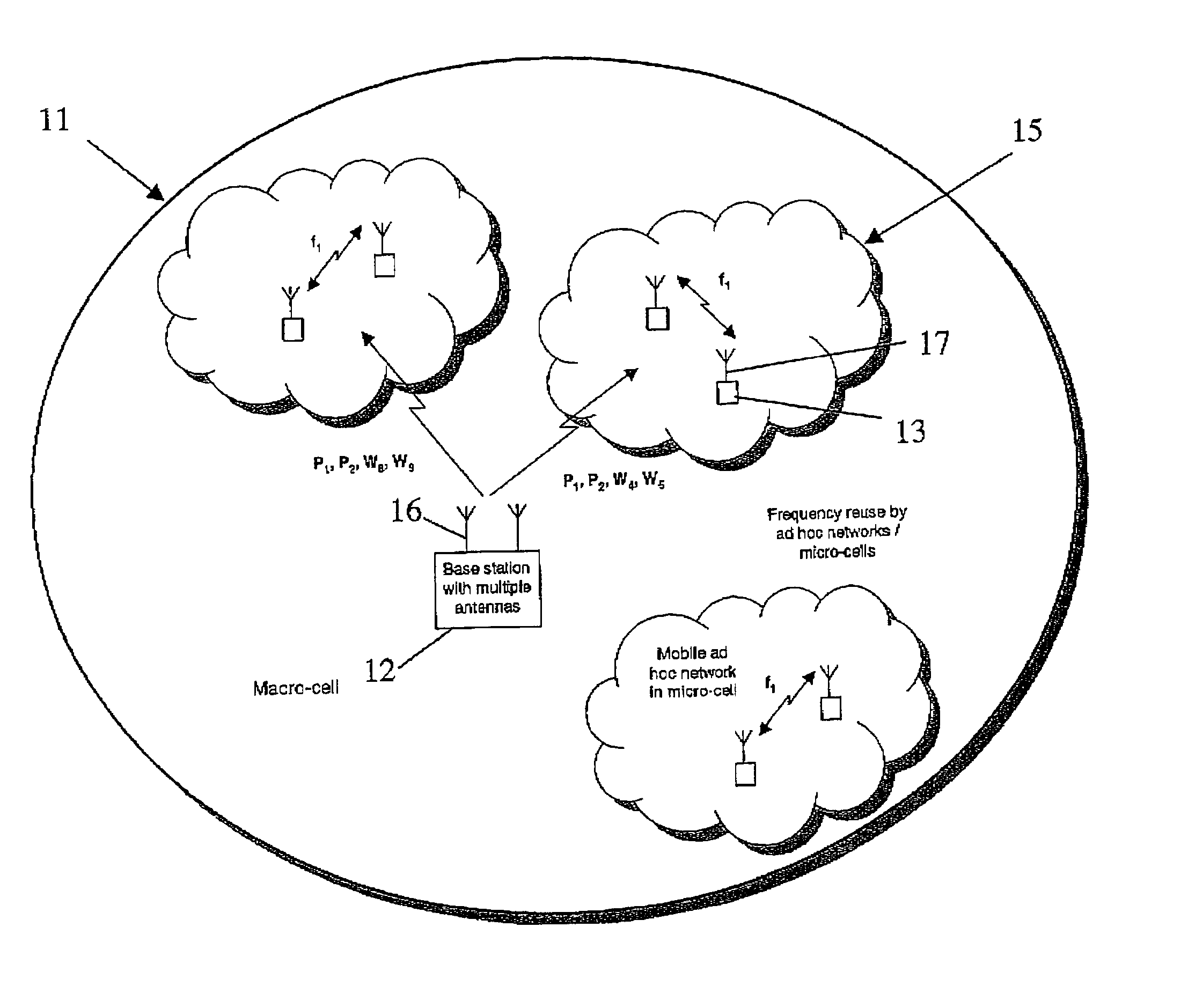
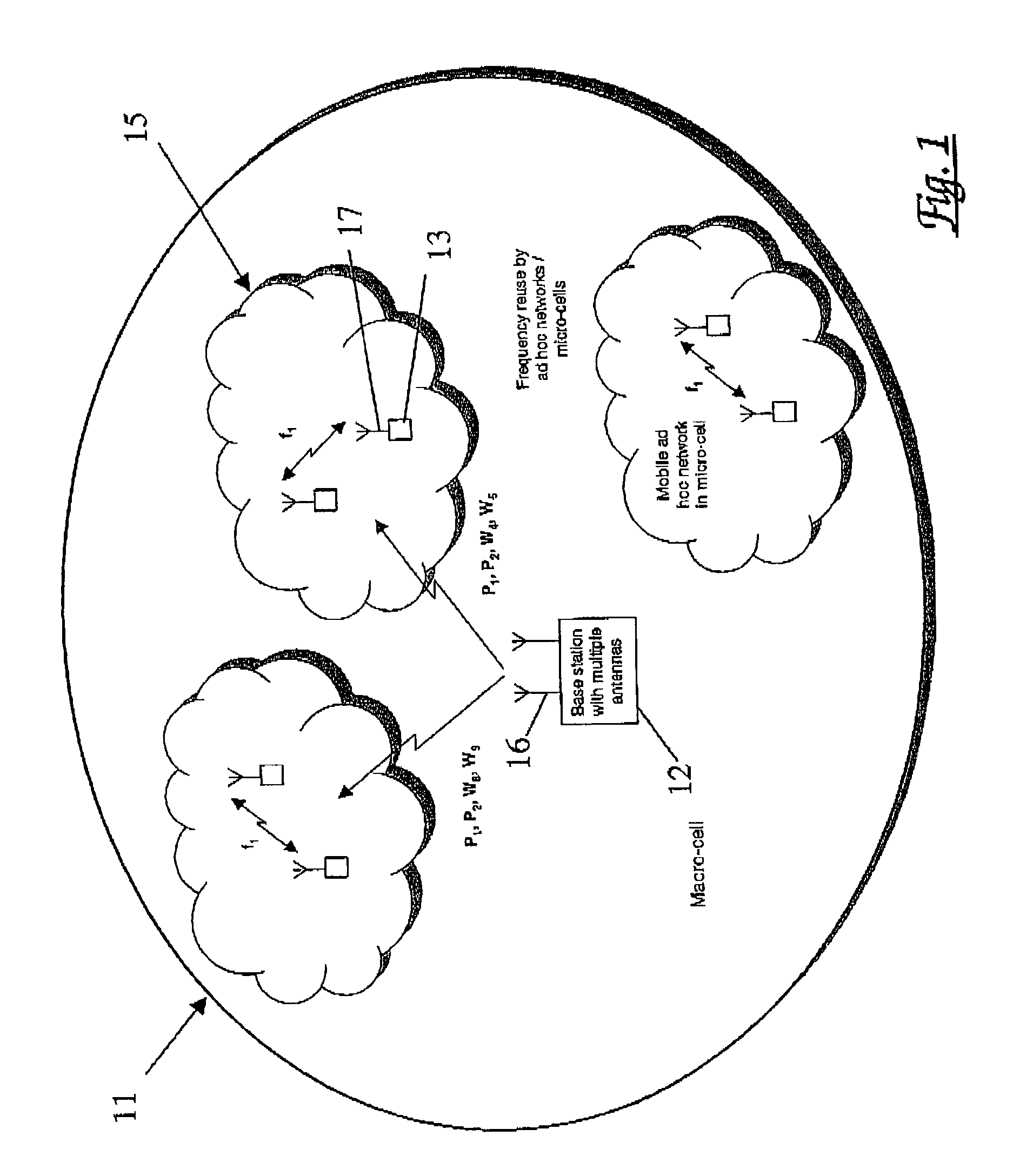
[0109] The transmitter is distributed, so that several terminals, each equipped with a single antenna, cooperate to enhance the signal transmitted to a multi-antenna base station. In this scenario, additional spectrum is required for communication between the cooperating terminals. The other terminals in the micro-cell are assumed to be similarly engaged in their own sessions, in addition to the signals required to be received and transmitted in respect of the first mobile terminal. Intra-cell communication is assumed to be digital.

[0110] For each bit of a signal from transmitter T to receiver R, 1 / m space-time symbols are transmitted. The relevant component of each of these space-time symbols must be passed from transmitter T to each of the m-1 other cooperating terminals in the group. These components are hard, rather than soft, symbols and so are encoded as {1, -1}, or one bit per symbol. Therefore, the total number of bits that must be transmitted by transmitter T to the (m-1) t...

example 3

[0119] EXAMPLE 3

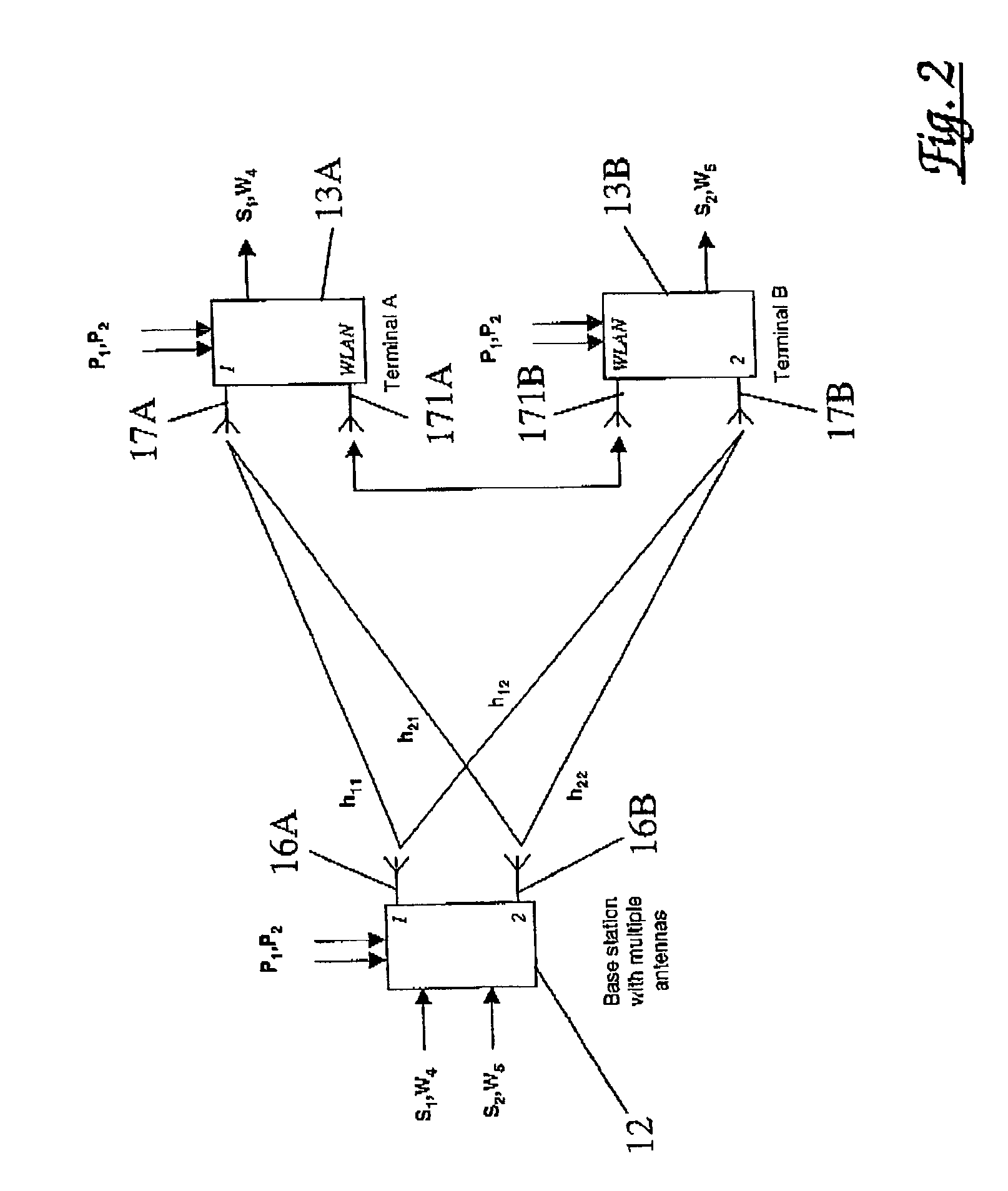
[0120] Both the transmit and the receive ends of the link are distributed, consisting of groups of cooperating terminals, in which each terminal is equipped with a single antenna. In this scenario, additional spectrum is required for communication between the cooperating terminals at both the transmitter and the receiver.

[0121] In this case, the proportion of the total spectrum required at the receive end of the link for intra-group communication is given by equations 8 and 9. At the transmit end, the corresponding proportion of the spectrum is described by equations 15 and 16. The total proportion of the spectrum that must be set aside for communication within the transmit terminal group and within the receive terminal group is the sum of the respective amounts, leading to 15 Rx S + Tx S = 1 1 + Rx+ 1 1 + Tx where Equation 19 Rx = 1 / ( 1 + m F ) m ( m - 1 ) log 2( k SNR 1 , 1) W S and Equation 20 Tx = 1 / m ( m - 1 ) W S Equation 21

[0122] Hence, the capacity gain t...

example 4

Distributed Receiver

[0127] We noted above that if cooperation is with idle terminals, rather than those engaged in their own sessions, the factor 1 / n in equation 5 and the factor 1 / m on the RHS of equation 7, do not apply. Although the total spectrum available for intra-terminal communication is given by 17 S = 1 1 + Equation 23

[0128] as before, the definition of a changes and equation 9 becomes 18 = 1 / ( 1 + m 2 F ) ( m - 1 ) log 2( k SNR 1 , 1) W S Equation 24

[0129] The relative capacity for a distributed system with m=n, then becomes 19 C m , nC 1 , 1= m ( 1 - 1 1 + ) Equation 25 C m , nC 1 , 1= m ( 1 1 + ( 1 + m 2 F ) ( m - 1 ) log 2( k SNR 1 , 1) W S ) Equation 26

[0130] The performance is shown in FIG. 9, which shows that the overall capacity gain is still dominated by the frequency re-use and spectral allocation, wherein:

4 Line F .kappa. SNR W .phi. S 91 100 10 10 10 4 1250 92 100 10 10 10 4 5000 93 1000 10 10 10 4 5000 94 1000 4 10 10 4 5000 95 1000 4 5 10 4 5000 96 1000 4 5...


PUM


Abstract

The invention is directed to a mobile communications system having improved spectral efficiency. The invention is further directed to methods and apparatus to achieve this improved spectral efficiency. In the mobile communications system communication with a plurality of mobile terminals is provided by a base station. Within the system terminals are adapted to communicate with one or more adjacent similar terminals to establish groups of terminals, called micro-cells. Each terminal within a micro-cell receives signals from the base station and then performs a first processing step on these signals. These processed signals are shared with all the other terminals within the micro-cell. Each terminal then performs a second processing step on the information it has received from all the other terminals within the micro-cell which enables it to derive a signal intended for reception by that terminal. The technique is applicable to both the uplink (user to base station) and the down link (base station to user) and also to peer to peer (user to user) communication.

Description

[0001] This invention relates to methods and apparatus for improving the spectral efficiency of mobile cellular communications systems. The invention also relates to a mobile communications system having such improved spectral efficiency.BACKGROUND TO THE INVENTION[0002] Mobile cellular operators are placing increasing demands on capacity in order to support greater numbers of subscribers and higher bit-rate services. This in turn is placing increasing pressure on the restricted amount of available radio spectrum. In attempts to provide more efficient use of the available spectrum, workers in this field have considered the use of spatial processing and of the provision of micro-cells.[0003] Spatial processing exploits the multi-path characteristics of the mobile radio channel by means of multiple antennas at the transmitter and at the receiver. The benefit arises in two ways. Firstly, there is a diversity gain, which arises provided the antennas at the receiver are sufficiently far ...

Claims


Application Information

Patent Timeline
Patent Type & Authority Applications(United States)
IPC IPC(8): H04L12/28H04L12/56H04W16/32
CPCH04B1/7097H04W16/06H04W16/32H04B2201/70702
Inventor NADEN, JAMES M.WARD, CHRISJEFFRIES, ANDREW W.
Owner APPLE INC
Why Eureka
Try Eureka