System and method for detection of zero current condition

Inactive Publication Date: 2005-01-25
INFINEON TECH AUSTRIA AG
View PDF10 Cites 8 Cited by
  • Summary
  • Abstract
  • Description
  • Claims
  • Application Information

AI Technical Summary

Benefits of technology

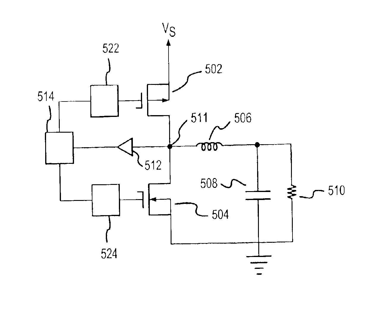
In one embodiment, the ZCD circuit may be used in a SPC that is configured as a buck converter having Field Effect Transistors (“FETs”) used as power switches. The ZCD signal may be used to maximize the efficiency of the system by controlling the operation of the FETs during DCM operation. In such a mann

Problems solved by technology

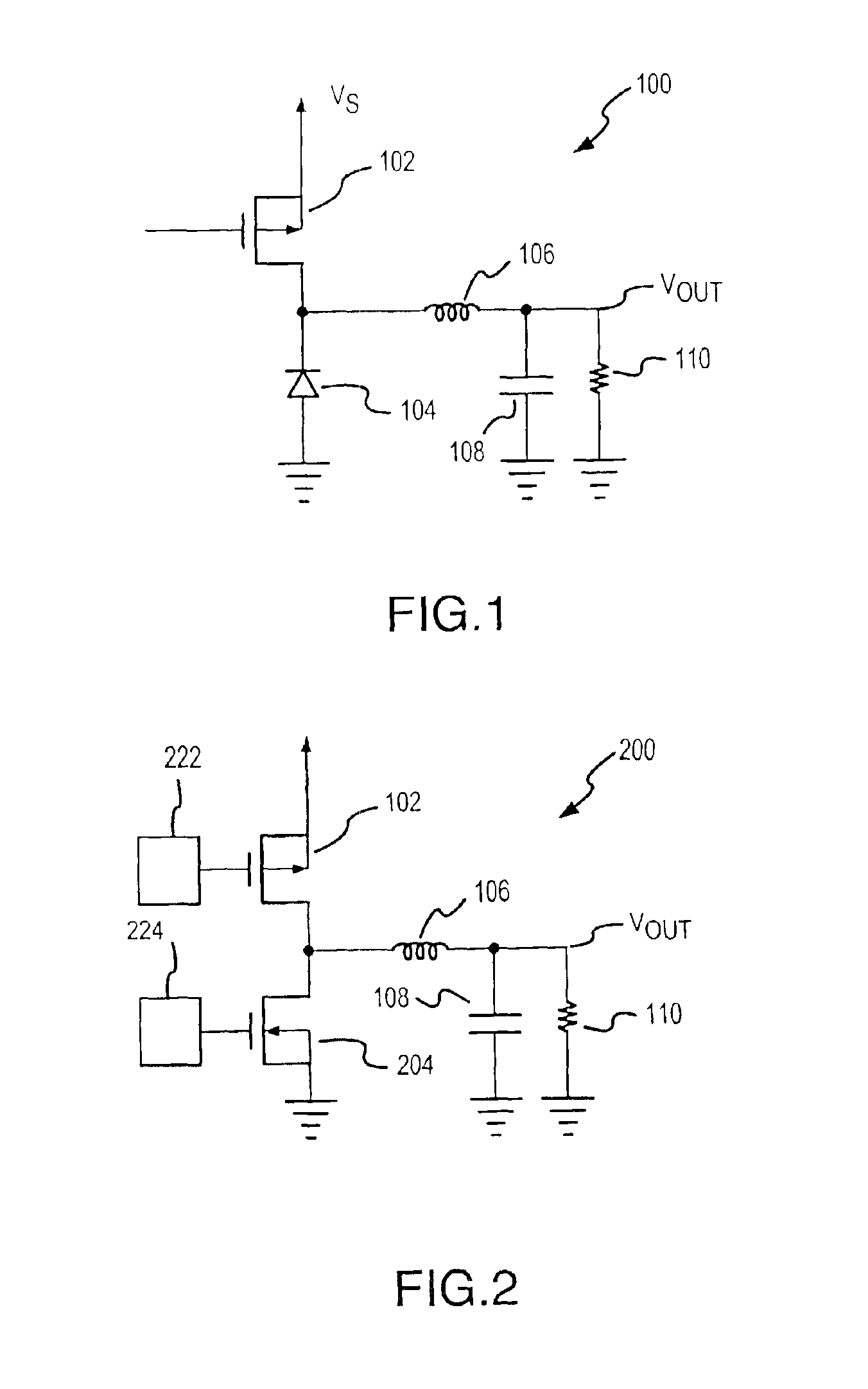
A problem of the buck power regulator is that, as low voltage outputs are required, the voltage drop of diode 104 leads to various consequences.
For example, the circuit becomes less efficient because of the voltage drop of approximately 0.7 volt across the diode.
Such inefficiencies become less tolerable when devices run

Method used


Image

  • System and method for detection of zero current condition
  • System and method for detection of zero current condition
  • System and method for detection of zero current condition

Examples


Embodiment Construction

The present invention may be described herein in terms of various functional components and various processing steps. It should be appreciated that such functional components may be realized by any number of hardware or structural components configured to perform the specified functions. For example, the present invention may employ various integrated components comprised of various electrical devices, e.g., resistors, transistors, capacitors, diodes, inductors, and the like, whose values may be suitably configured for various intended purposes. In addition, the present invention may be practiced in any integrated circuit application where a detection of a zero current flow is desired. Such general applications that may be appreciated by those skilled in the art in light of the present disclosure are not described in detail herein. Further, it should be noted that while various components may be suitably coupled or connected to other components within exemplary circuits, such connec...


PUM


Abstract

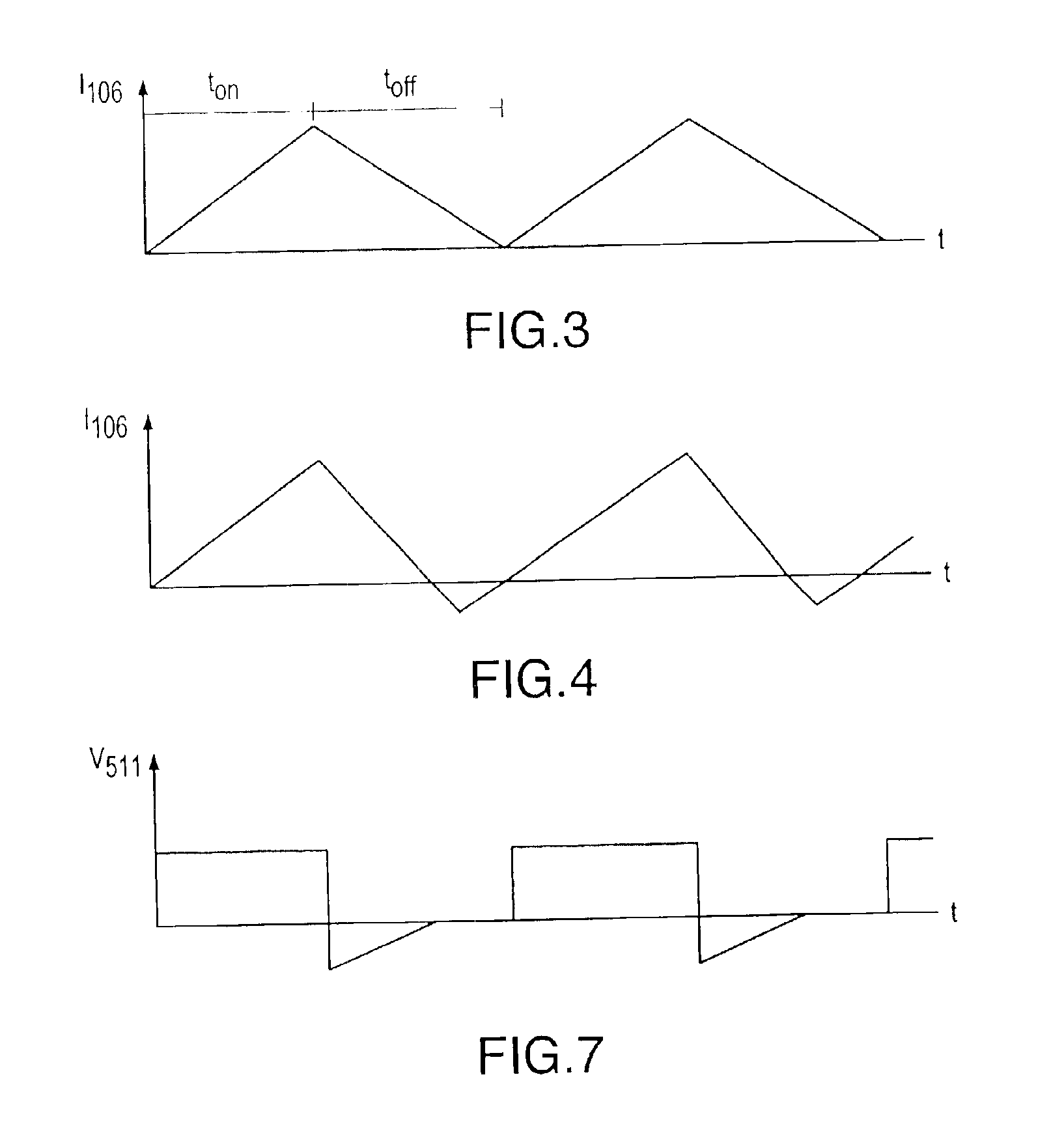
A method for converting power includes charging an inductor by coupling the inductor to a voltage source for a predetermined amount of time. Thereafter, the inductor is discharged by coupling the inductor to a ground until the current flowing through the inductor equals zero. A method for detecting a zero current flowing through the inductor includes coupling the inductor to a transistor and comparing the output of that transistor to a transistor coupled to ground.

Description

FIELD OF INVENTIONThis application relates generally to electronic circuits and more particularly to an electronic circuit for detecting a zero current condition, where such a circuit can be used in voltage regulators and switching power converters (“SPC”), including multiphase power converters.BACKGROUND OF THE INVENTIONPower regulators are often used in electronic equipment to supply power at a predetermined voltage to a system. For example, a typical desktop computer may contain a power supply that converts alternating current (“AC”) from a wall socket, to direct current (“DC”) with a voltage that is usable by the various components of the computer system. With continued reference to computer systems, a hard disk drive may require a 12 volt (“V”) power input, while various integrated circuit components may require, for example, power at 5.0 V, 3.3 V, or 1.5 V. A power supply must thus contain power regulators to generate the required voltage levels.Buck power regulators are often...

Claims


Application Information

Patent Timeline
IPC IPC(8): G01R19/175H02M3/158H02M1/04H02M3/04H02M1/02H02M3/156H02M1/08
CPCG01R19/175H02M1/083H02M3/156H02M3/1588H02M3/1584Y02B70/1466H02M2001/0009H02M1/0009Y02B70/10
Inventor SUSAK, DAVIDGOODFELLOW, RYAN
Owner INFINEON TECH AUSTRIA AG
Why Eureka
Try Eureka