Conveyor drive system and motor built-in reducer therefor

a technology of drive system and reducer, which is applied in the direction of toothed gearings, packaging, gearings, etc., can solve the problems of rattling noise, unreachable improvement, and unreachable noise from not only the chain but also the geared motor

Inactive Publication Date: 2003-07-17
SUMITOMO HEAVY IND LTD
View PDF4 Cites 25 Cited by
  • Summary
  • Abstract
  • Description
  • Claims
  • Application Information

AI Technical Summary

Problems solved by technology

While the demand for such conveyor has been growing, no improvements have been made so far that address this problem.
As a result, the chain moves around the driving and driven sprockets as if discretely, making a rattling noise.
Recent use however of an inverter power supply with converting frequency which enables a variable speed drive of a motor has brought about a problem of unexpected noise from not only the chain but also from the geared motor and its neighboring constituents such as a bed on which the geared motor is placed, or supporting legs and bases.
This noise is apparently caused by resonance between the chain or timing belt and the driving geared motor, which occurs at certain rpm of the motor.
The inventors have ascertained through research that this problem is likely to occur particularly when the chain sprocket has a small pitch circle diameter.
It is however, not easy to take appropriate measures to prevent noise or vibration which is generated unexpectedly depending on the situation.
This is because it is not desirable in terms of cost to provide measures taken to prevent such unexpected noise or vibration, which result in excessive quality during the majority of the operation period.
These measures however increase the equipment costs and require more space to install the system.
However, the structure of the analogue power transmission does not allow a large torque to be transmitted, and accordingly the overall mechanism tends to be bulky.
Also, the problem of slippage at the belt-to-pulley interface which is intrinsic to this mechanism makes it hard to perform feed-forward or feed-back control, and therefore precise positioning or control of speed is impossible.

Method used


Image

  • Conveyor drive system and motor built-in reducer therefor
  • Conveyor drive system and motor built-in reducer therefor
  • Conveyor drive system and motor built-in reducer therefor

Examples


third embodiment

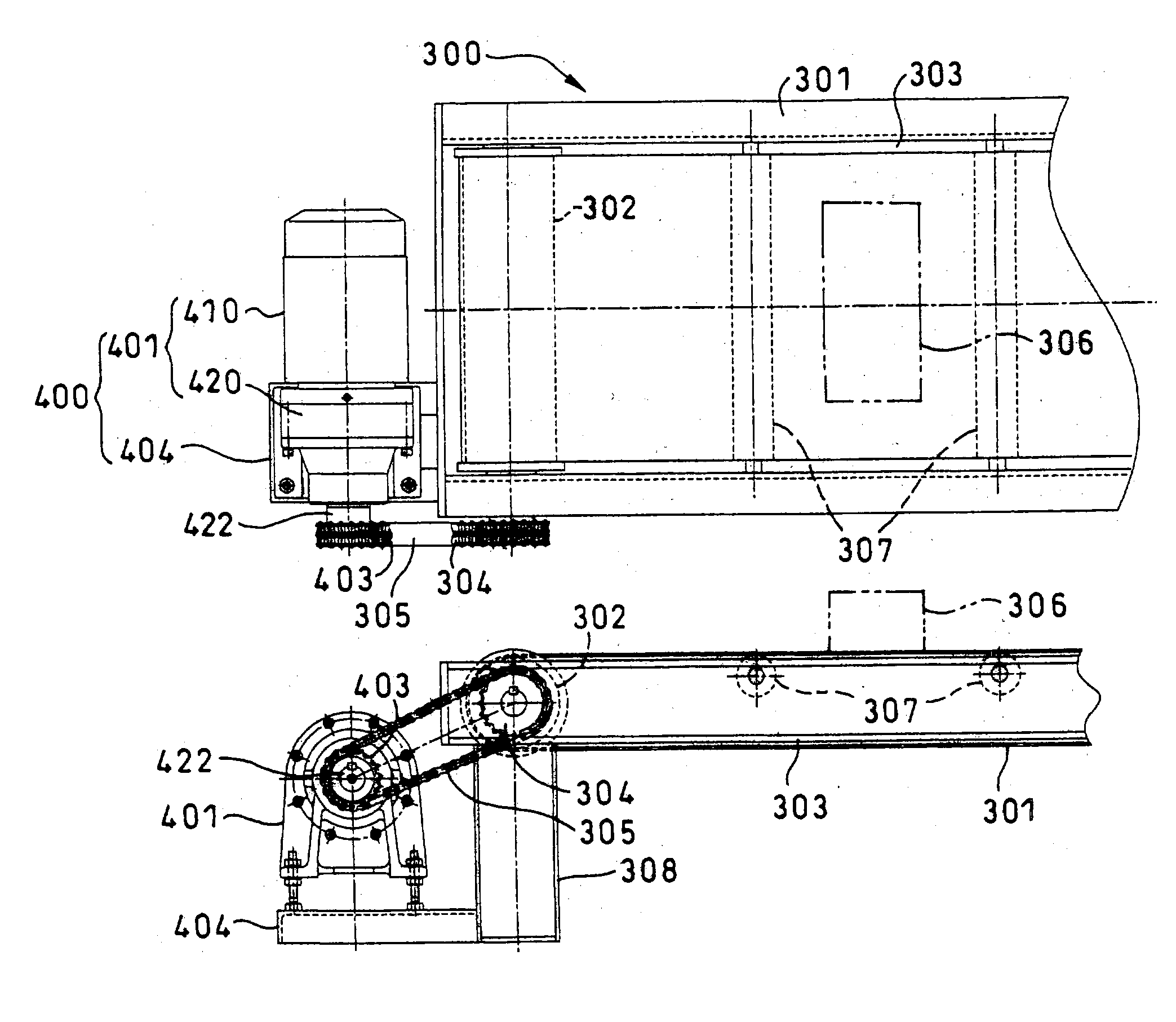
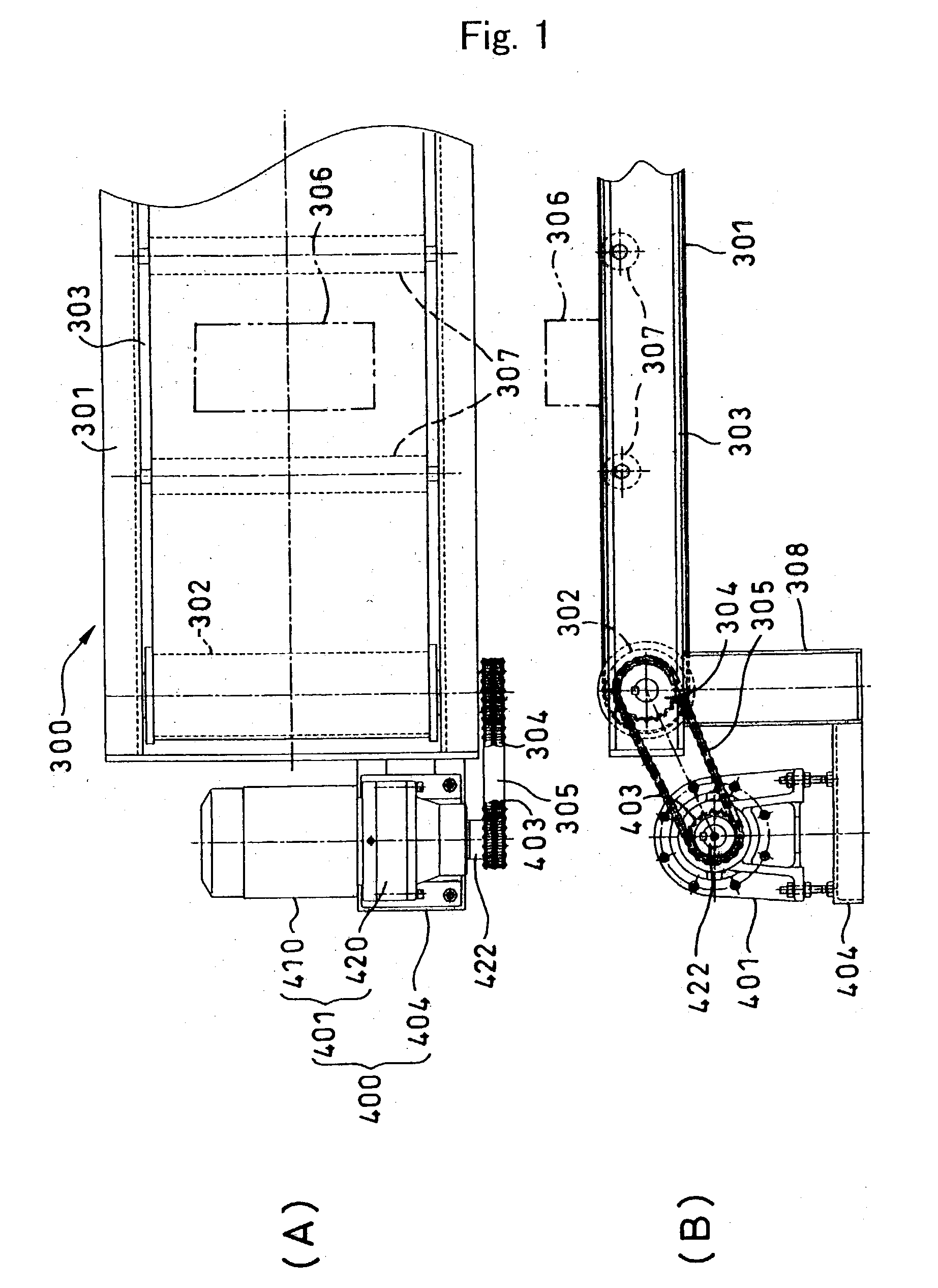
[0055] FIG. 7 is a cross section of a conveyor and a conveyor belt drive system according to the present invention. In this embodiment, instead of the chain 305 for transmitting driving power, a toothed timing belt 700 made of rubber or plastic is employed. In order to install the timing belt 700, a toothed driven belt pulley 701 and a toothed driving belt pulley 702 are used in place of the driven sprocket 304 and drive sprocket 403.

fourth embodiment

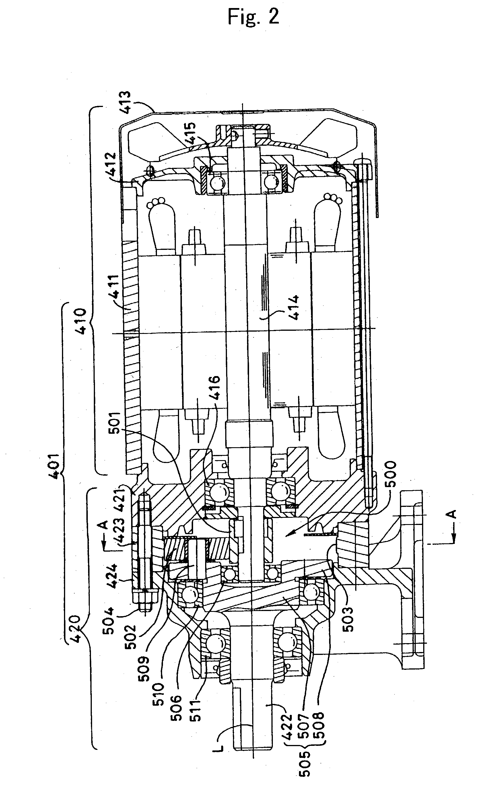
[0056] FIG. 8 is a cross section of a conveyor and a conveyor belt drive system according to the present invention. This embodiment employs the belt and pulley structure as the previous embodiment shown in FIG. 7. In addition, two sets of simple planetary roller mechanisms 802 and 803 are equipped in the reduction gear unit 801 constituting the motor built-in reducer 800, thereby enabling to achieve a wider range of reduction ratio.

[0057] As described above, the conveyor and the conveyor belt drive system using a chain or a timing belt and a motor built-in reducer according to the present invention employs a simple planetary roller-type, motor built-in reducer as the power source. This eliminates resonance resulting from a polygonal motion of the chain or timing belt as it runs around the sprockets or pulleys while bending. The noise is thereby much reduced and also the system is made more compact.


PUM


Abstract

A compact conveyor drive system which prevents resonance-induced noise and vibration caused by a polygonal motion observed in transmission gearing. The conveyor belt of the conveyor is driven through a chain trained over a driven sprocket mounted to the shaft of a drum and a drive sprocket on the side of a motor. The drive system is a motor built-in reducer, and a simple planetary roller mechanism is employed for the reducer. This enables the diameter of the sprockets to be made smaller. The motor generates lower vibration, while providing sufficient torque.

Description

[0001] 1. Field of the Invention[0002] The present invention relates to conveyor drive systems, in particular, to a conveyor drive system with lowered vibration, noise, or pulsation, and a motor built-in reducer used for the conveyor drive system.[0003] 2. Description of the Related Art[0004] FIG. 9A is a top plan view and FIG. 9B is a front view of a prior art conveyor drive system, in which the reference numeral 100 denotes a conveyor and the reference numeral 200 denotes a drive system therefor.[0005] The conveyor 100 includes a bed 101, a pair of drums 102 rotatably supported at both ends of the bed 101, and an endless conveyor belt 103 trained over both drums 102. The drawings illustrate only one end of the bed 101 and one of the drums 102. A driven sprocket 104 is coupled to the shaft of the illustrated drum 102, so that the drum 102 is driven by a geared motor 201 via a chain 105 trained over the driven sprocket 104. The reference numerals 106, 107, and 108 in the drawings re...

Claims


Application Information

Patent Timeline
Patent Type & Authority Applications(United States)
IPC IPC(8): B65G23/22B65G23/24F16H1/28
CPCB65G23/22B65G2207/32B65G23/24
Inventor WATANABE, HIROSHIMINEGISHI, KIYOJITAMENAGA, JUN
Owner SUMITOMO HEAVY IND LTD
Why Eureka
Try Eureka