Integrated fuel cell and electrochemical power system employing the same

Inactive Publication Date: 2003-07-17
METALLIC POWER INC
View PDF3 Cites 48 Cited by
  • Summary
  • Abstract
  • Description
  • Claims
  • Application Information

AI Technical Summary

Problems solved by technology

However, button cells, despite their small size, still cannot easily fit onto integrated circuits.
Moreover, button cells must be replaced after discharge, and are therefore of limited effe

Method used


Image

  • Integrated fuel cell and electrochemical power system employing the same
  • Integrated fuel cell and electrochemical power system employing the same
  • Integrated fuel cell and electrochemical power system employing the same

Examples


first embodiment

[0069] Referring to FIG. 3, the invention comprises a fuel cell integrated on or into a unitary planar substrate 340. In one example, the planar substrate 340 is a semiconductor substrate in which cavities or wells are formed through subtractive processes such as etching or patterned etching. Control or load circuitry may also be integrated on the same substrate. The fuel cell comprises an anode cavity 318 integrated on or into the substrate 340 that is capable of holding a fuel. When the fuel cell is in operation, in the case of a metal fuel cell, the fuel in the cavity may form at least a portion of the anode of the fuel cell. Referring to FIG. 4, the cavity 318 has one or more regions of ingress and egress, identified with numerals 332 and 334 respectively, for the fuel and reaction products.

[0070] Referring back to FIG. 3, an optional cathode well 320 extends into a surface of the planar substrate 340 and is in general proximity to the anode cavity 318. A cathode 322 is situated...

second embodiment

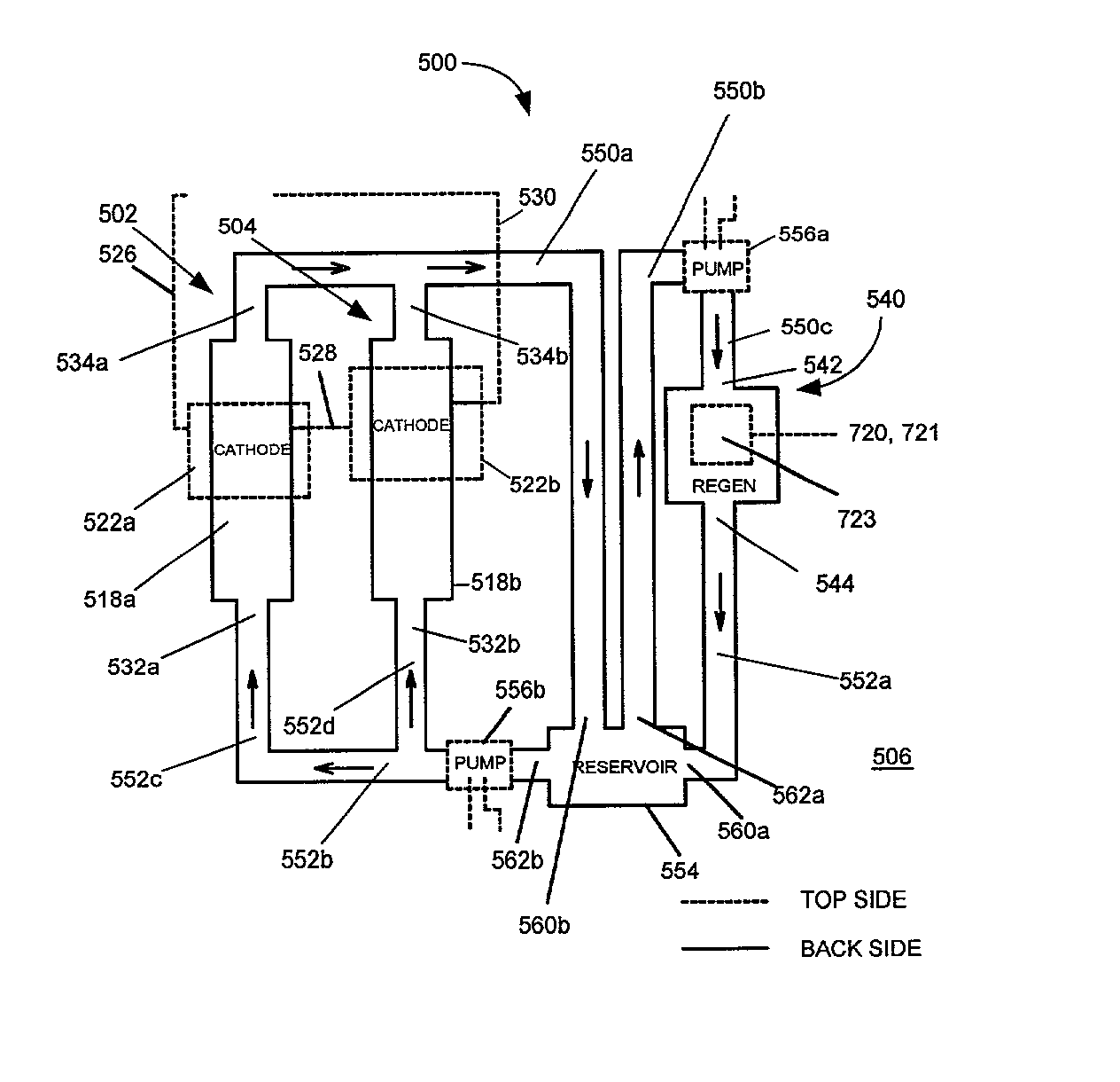
[0073] Referring to FIG. 5, the invention comprises an electrochemical power system 500. The system 500 in turn comprises one or more fuel cells 502, 504, a regeneration unit 540 servicing the fuel cells 502, 504, and a reservoir 554 for the storage of fuel regenerated by the regeneration unit 540. The fuel cells 502, 504, the regeneration unit 540, and the reservoir 554 can each be integrated on or into a substrate 506. For purposes of illustration only, two fuel cells 502, 504 are shown coupled in series in the system 500 of FIG. 5, and one regeneration unit 540 is shown servicing the two fuel cells 502, 504. However, it should be appreciated that embodiments of system 500 are possible employing one or more than two fuel cells, coupled in series or parallel, or connected to different loads altogether. Moreover, embodiments are possible which employ more than one regeneration unit or which do not employ a reservoir, at least one which is separated from the regeneration unit. Accord...

third embodiment

[0086] the invention comprises a metal fuel cell integrated on or into a substrate where the fuel cell has a like structure and configuration as the fuel cells 502, 504 described above in relation to the system 500 illustrated in FIG. 5, but with the additional requirement that the portions of the interior of the anode cavity, and the regions of ingress and egress thereto, which come in contact with the reaction medium employed in the metal fuel cell, be substantially chemically inert with respect to the reaction medium. These areas may be inherently substantially chemically inert, or may be rendered substantially chemically inert through various means, such as layering these areas with a layer of a substantially chemically inert substance, or by suitable doping of these areas. Such substances or dopants generally depend on the reaction medium used, but, in the case of a potassium hydroxide solution, a suitable chemically inert substance for coating is PTFE.


PUM


Abstract

An electrochemical power system including one or more fuel cells integrated on or into a substrate is described. For each fuel cell, at least two stacked layers comprising a cathode layer and an ion exchange layer are situated within the substrate. A first access path for allowing an oxidant to access the cathode layer is provided from one side of the substrate, and a second access path for allowing a fuel or a reaction medium containing a fuel to access a layer in the stack is provided from the other side of the substrate. A third access path, which may be the same or different from the second access path, allows egress of one or more reaction products from the layer. A first conductor connects to the cathode, and a second conductor connects to the second access path or the layer in the stack accessible through the second access path. A regeneration unit for regenerating fuel from one or more reaction products also can be integrated on or into the substrate. The regeneration unit comprises a reaction chamber with one or more areas of ingress and one or more areas of egress. A first flow path interconnects the one or more areas of egress of the reaction chamber with the second access path of the one or more fuel cells. A second flow path interconnects the third access path of the one or more fuel cells with the one or more areas of ingress of the reaction chamber.

Description

[0001] This invention relates generally to fuel cells, and, more specifically, to fuel cells and electrochemical power systems employing fuel cells which are integrated on or into a substrate such as a semiconductor substrate.RELATED ART[0002] Integrated circuits (ICs) today fulfill diverse applications and uses, ranging from incorporation into medical devices for implantation or insertion into the human body, use in credit cards, use in conjunction with merchandise for tracking purposes, and use in miniature consumer electronics.[0003] Traditionally, ICs are powered by batteries such as button cells. However, button cells, despite their small size, still cannot easily fit onto integrated circuits. Moreover, button cells must be replaced after discharge, and are therefore of limited effectiveness.[0004] Fuel cells can be attractive alternatives to traditional energy sources such as batteries because they can be refueled after discharge with fuel regenerated from the reaction product...

Claims


Application Information

Patent Timeline
IPC IPC(8): B05D5/12H01M8/00H01M8/02H01M8/04H01M8/08H01M8/10H01M8/18H01M8/24H01M12/06H01M16/00
CPCH01M8/0269H01M8/04201H01M8/1097H01M8/186Y02E60/528H01M8/241H01M12/06H01M16/003Y02E60/521H01M8/188Y02E60/50H01M8/2418
Inventor GRANDE, WENDY C.COLBORN, JEFFREY A.
Owner METALLIC POWER INC
Why Eureka
Try Eureka