
Adapter for electrical plug-in connections on fuel-injection valves

a technology for plug-in connections and fuel injectors, which is applied in the direction of coupling device connections, machines/engines, mechanical equipment, etc., can solve the problems of long setup times and high manufacturing costs

Inactive Publication Date: 2003-07-17
ROBERT BOSCH GMBH
View PDF2 Cites 3 Cited by
  • Summary
  • Abstract
  • Description
  • Claims
  • Application Information

AI Technical Summary

Benefits of technology

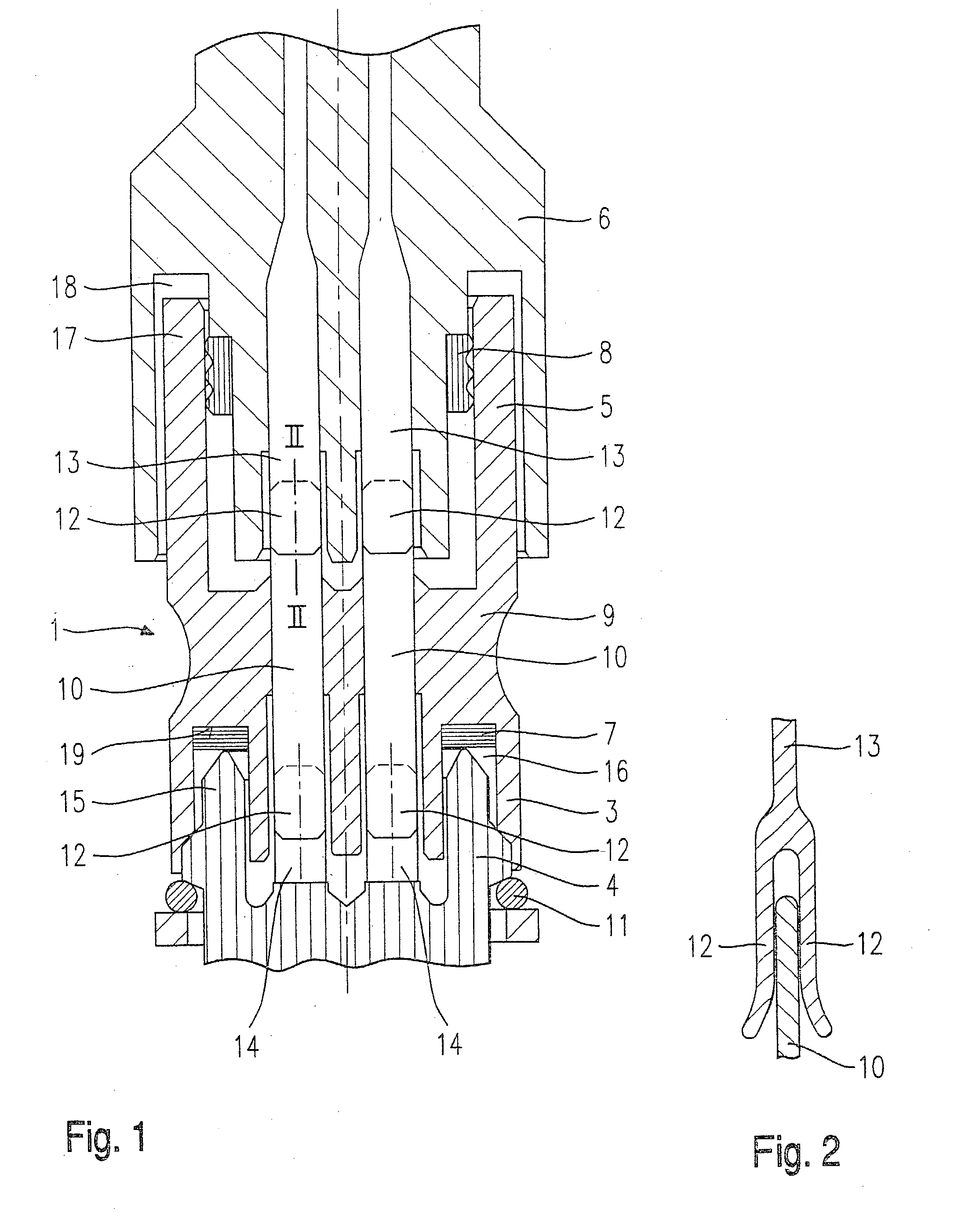
[0004] The adapter according to the present invention for electrical plug-in connections for a fuel injector having the features of the main claim has the advantage over the related art that changes in the shape of the counterplug only require changes in the shape of the adapter, which may be implemented easily, and therefore rapidly and cost-effectively, but not in the shape of the plug-in connector of the fuel injector.[0005] In addition, the adapter is distinguished by a reliable seal of the electrical contacts in relation to the surroundings.[0006] Advantageous refinements and improvements of the adapter indicated in the main claim are possible through the measures described in the subclaims.[0007] It is also advantageous that seals between the counterplug and the adapter and / or between the adapter and the plug-in connector of the fuel injector may be implemented variably as radial or axial seals, depending on the requirements placed on the plug-in connector.[0008] The elastic spring shackles on the ends of the contact tabs of the adapter, the counterplug, and / or the plug-in connector ensure, through clamping, a reliable contact and protection against unintended detachment of the plug-in connection.[0009] The adapter is advantageously secured on the plug-in connector of the fuel injector by a spring buckle, through which easier connectability to the counterplug of the electrical line may be achieved.

Problems solved by technology

The high manufacturing outlay which is required if changes are to be implemented on the plug or on the plug-in connector of the fuel injector is disadvantageous in known plug-in connection systems.
Thus, for example, the requirements of different clients, caused by differently shaped plugs which are specific to the client, may only be implemented using different injection molds and extensive mounting and demounting of the molds, which results in long setup times.

Method used


Image

  • Adapter for electrical plug-in connections on fuel-injection valves
  • Adapter for electrical plug-in connections on fuel-injection valves

Examples


Embodiment Construction

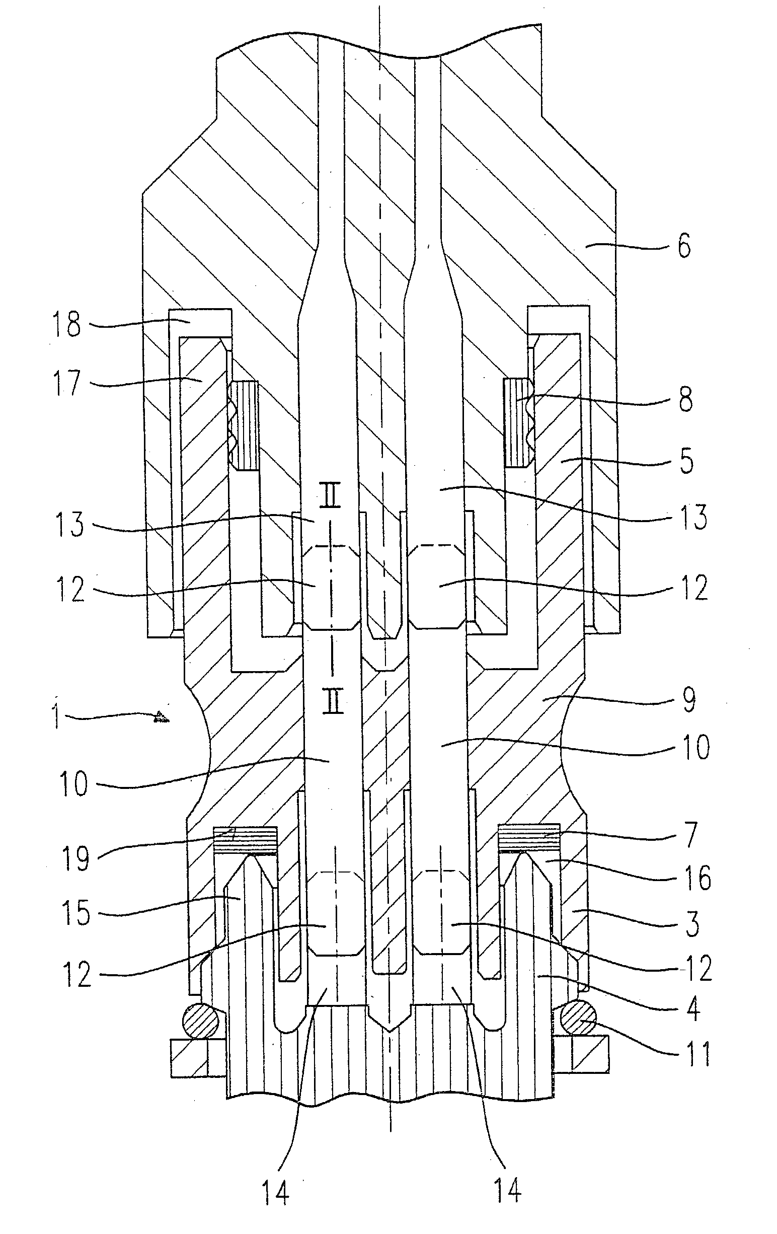
[0013] FIG. 1 shows a schematic sectional illustration of a view of an adapter 1 implemented according to the present invention for connecting a plug-in connector 4 of a fuel injector to a counterplug 6 of an electrical line, which leads, for example, to an electronic control unit (not shown). Counterplug 6 is connectable to the fuel injector via adapter 1 and permits the electrical contact for actuating the fuel injector.

[0014] Adapter 1 is implemented in this case in the shape of a round or oval cylindrical body 9, whose first end 3 may be plugged into plug-in connector 4 of the fuel injector and whose second end 5 may be plugged into counterplug 6 of the electrical line.

[0015] Plug-in connector 4 of the fuel injector is implemented in this case in the shape of a sleeve 15, which is preferably made of plastic and is also sprayed during spray coating of the fuel injector. In this case, sleeve 15 projects over contact tabs 14, necessary for producing the contact, which are connected...


PUM


Abstract

An adapter (1) is described for connecting an electrical plug-in connector (4) of a fuel injector to a counterplug (6), whose first end (3) is pluggable into a plug-in connector (4) of the fuel injector and whose second end (5) is pluggable into counterplug (6) of the electrical line. A first seal (7) being positioned between the first end (3) of the adapter (1) and the plug-in connector (4) of the fuel injector and a second seal (8) being positioned between the second end (5) of the adapter (1) and the counterplug (6).

Description

BACKGROUND INFORMATION[0001] The present invention is directed to an adapter for electrical plug-in connections on fuel injectors according to the definition of the species in the main claim.[0002] The electrical contact between an actuator of a fuel injector and the voltage source is typically produced via a plug-in connection system, in which the plug is shaped so that it may be plugged in a form-fitting way into the plug-in connector on the fuel injector. The plug and the plug-in connector are producible in this case from plastic, using injection molding. The plug-in connection is additionally to be designed so that the electrical contacts are sealed in relation to the surroundings to protect against corrosion, in order to counteract subsequent contact weaknesses.[0003] The high manufacturing outlay which is required if changes are to be implemented on the plug or on the plug-in connector of the fuel injector is disadvantageous in known plug-in connection systems. Thus, for examp...

Claims


Application Information

Patent Timeline
IPC IPC(8): F02M51/00F02M51/02F02M51/06H01R13/52H01R31/06
CPCH01R13/5219
Inventor LUFT, HEINZ
Owner ROBERT BOSCH GMBH
Learn More