

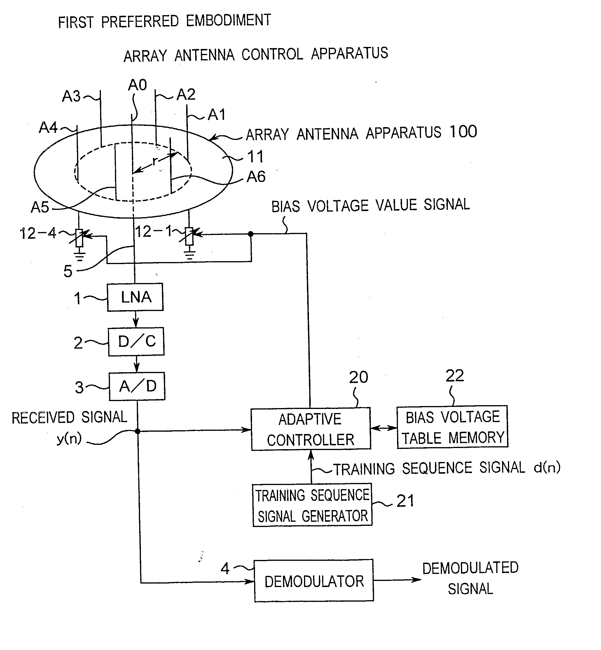
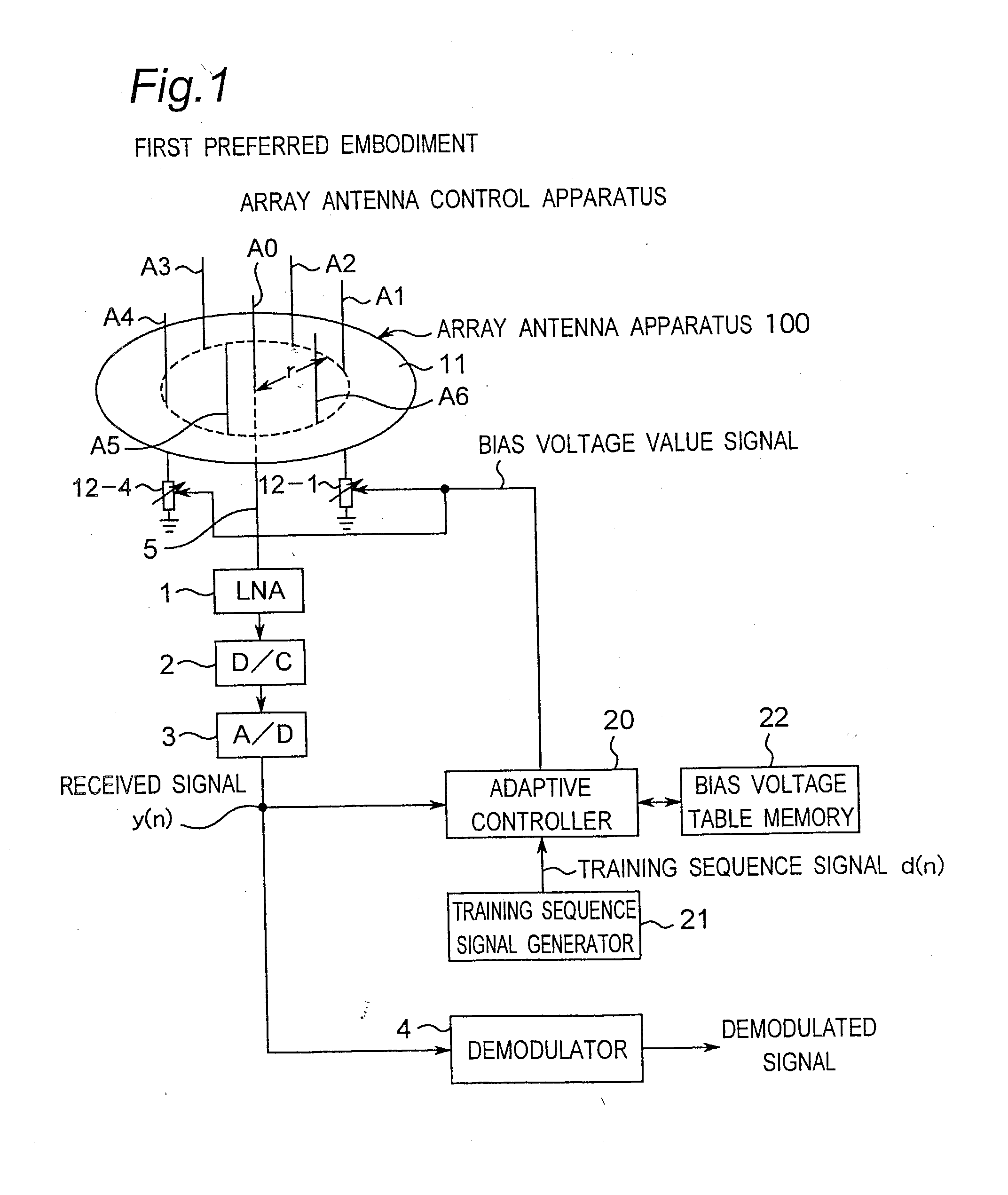
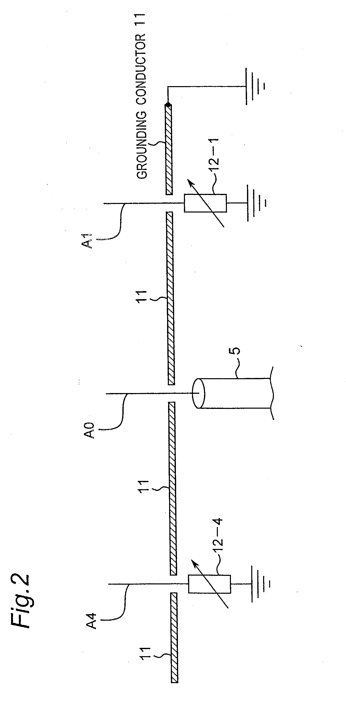
Method for controlling array antenna equipped with single radiating element and a plurality of parasitic elements
a technology of array antenna and parasitic element, which is applied in the direction of antenna array, electrical apparatus, antennas, etc., can solve the problems of increasing the number of calculations, the inability to observe any signal on a passive element, and the inability of most methods prepared for conventional adaptive arrays to directly apply to the espar antenna
- Summary
- Abstract
- Description
- Claims
- Application Information
AI Technical Summary
Benefits of technology
Problems solved by technology
Method used
Image

Examples
Embodiment Construction
s
[0354] As described in detail hereinabove, according to a method for controlling an array antenna according to a preferred embodiment of the present invention, in the method for controlling an ESPAR antenna, the method is characterized in including a step of iterating the following steps of: upon setting the reactance values of the respective variable-reactance elements by randomly perturbing the reactance values from predetermined initial values, calculating predetermined cross correlation coefficients between a received signal and a training sequence signal before and after the perturbation, the received signal being obtained by receiving by the array antenna a training sequence signal contained in a radio signal transmitted from a remote transmitter, and the training sequence signal being generated so as to have a signal pattern identical to that of the transmitted training sequence signal; selecting and setting reactance values when the cross correlation coefficient increases b...
PUM
 Abstract
Description
Claims
Application Information