Injection molding nozzle

a technology of injection molding and nozzle, which is applied in the direction of dough shaping, application, food shaping, etc., can solve the problems of air leakage around the manifold bushing, large fire risk, air leakage at the back-up pad/cylinder housing and between the threads, etc., to reduce waste and maintenance costs, increase the maximum operating injection pressure, and reduce the cost of producing the nozzle

Inactive Publication Date: 2003-07-31
HUSKY INJECTION MOLDING SYST LTD
View PDF0 Cites 38 Cited by
  • Summary
  • Abstract
  • Description
  • Claims
  • Application Information

AI Technical Summary

Benefits of technology

0030] With this arrangement, air leakage from between the back-up pad 14 and the manifold bushing 30 has been substantially eliminated. For a given size injection molding nozzle, the maximum operating injection pressure has been increased and the cost to produce the nozzle has been reduced. Leakage of the molten material between the manifold bushing 30 and the manifold 52 has also been substantially reduced, which reduces waste and maintenance cost associated with the injection molding machine.

Problems solved by technology

However, due to the threads and imperfect mating surfaces, air may leak around the manifold bushing.
The close proximity of flammable hydraulic oil to the heated manifold 1 means that there is a great risk of fire with this design after the seals have worn.
This construction is also disadvantageous in that the nozzle assembly must travel laterally with the manifold as it thermally expands.
Other problems encountered with current injection molding nozzles include air leakage at the back-up pad / cylinder housing and between the threads on the jam nut and the injection nozzle.
Induced stresses from the jam nut reduce the maximum injection pressure the injection nozzle can withstand, thereby adversely limiting the acceptable operating range for a given nozzle size.

Method used


Image

  • Injection molding nozzle
  • Injection molding nozzle
  • Injection molding nozzle

Examples


Embodiment Construction

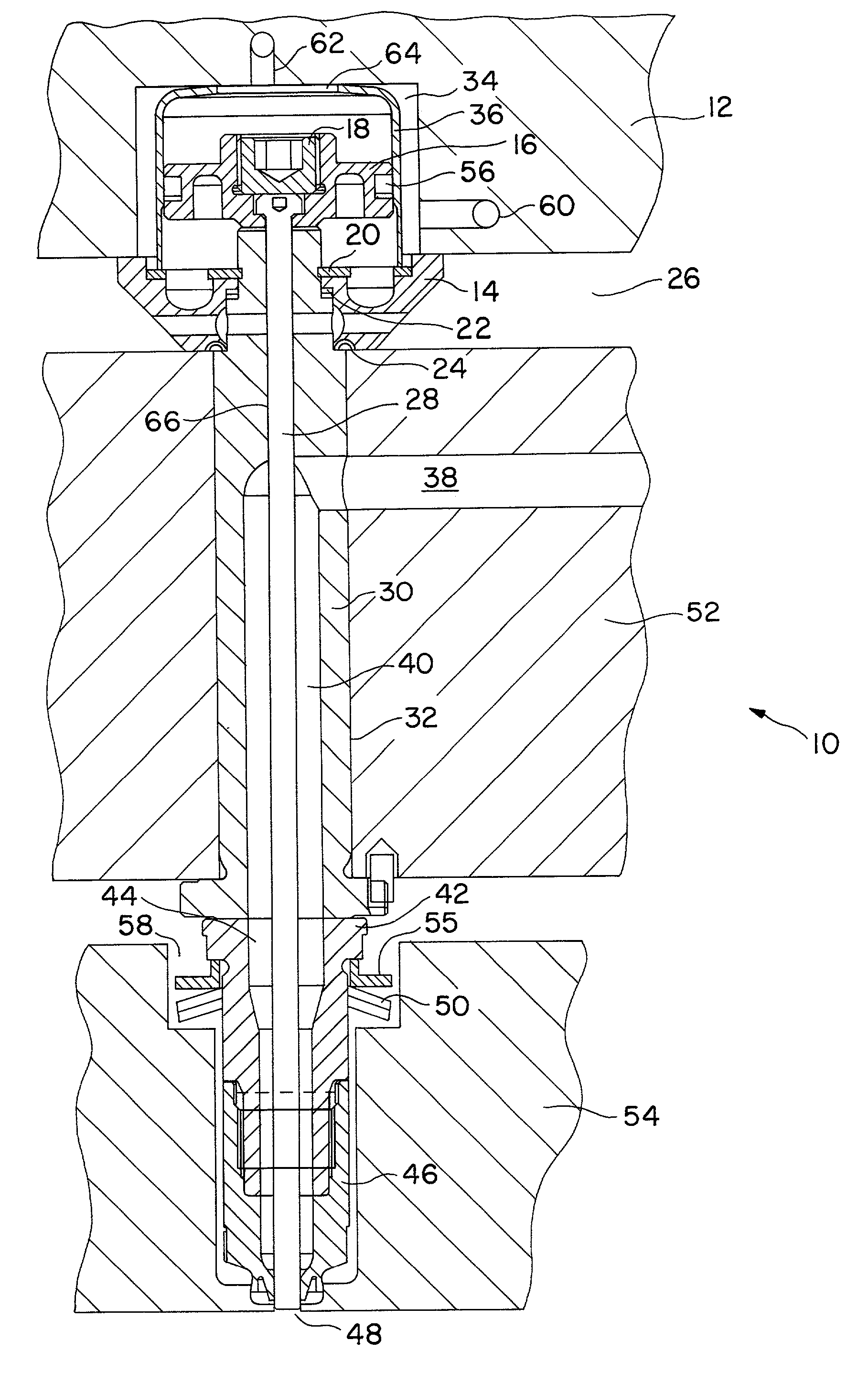
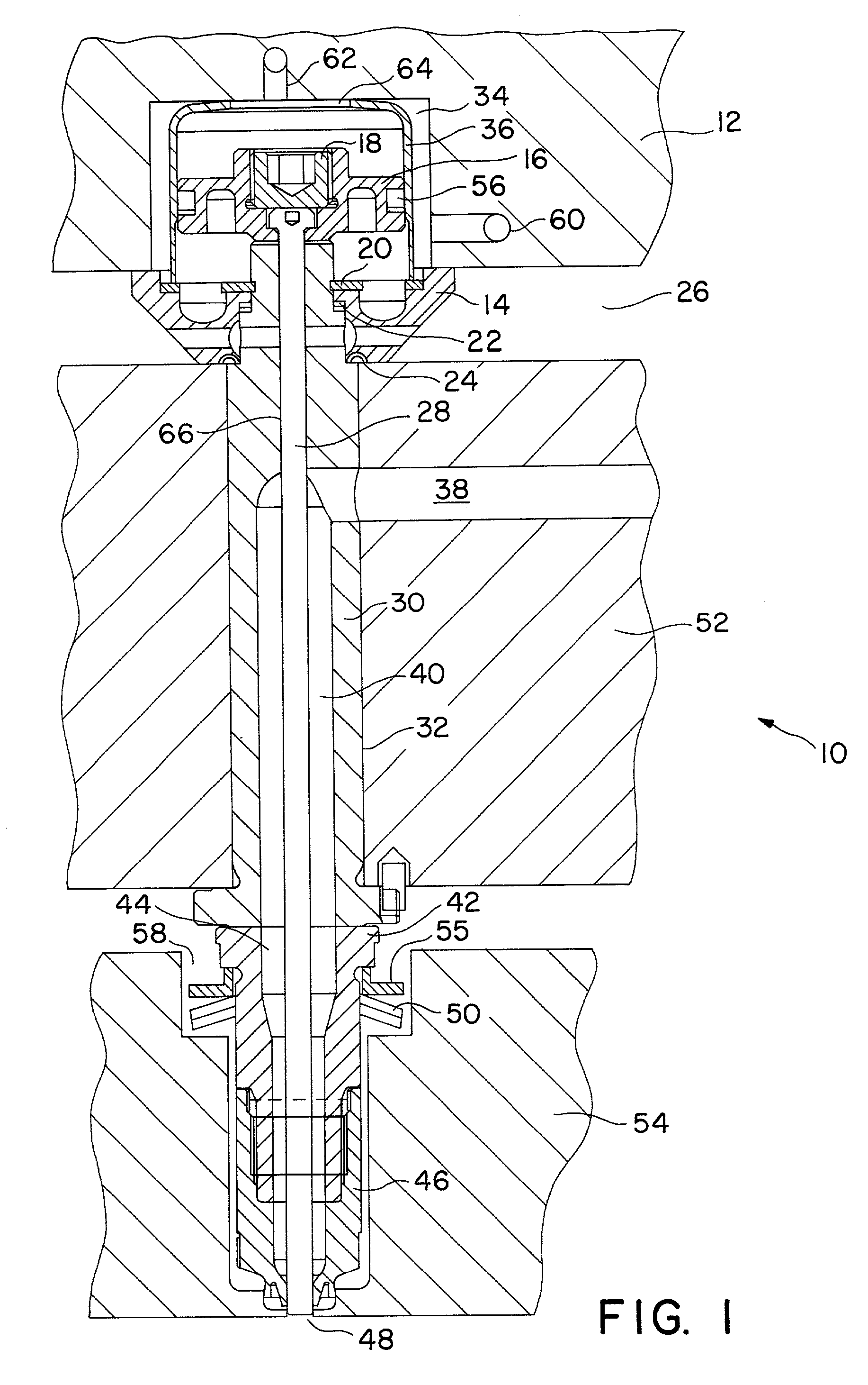
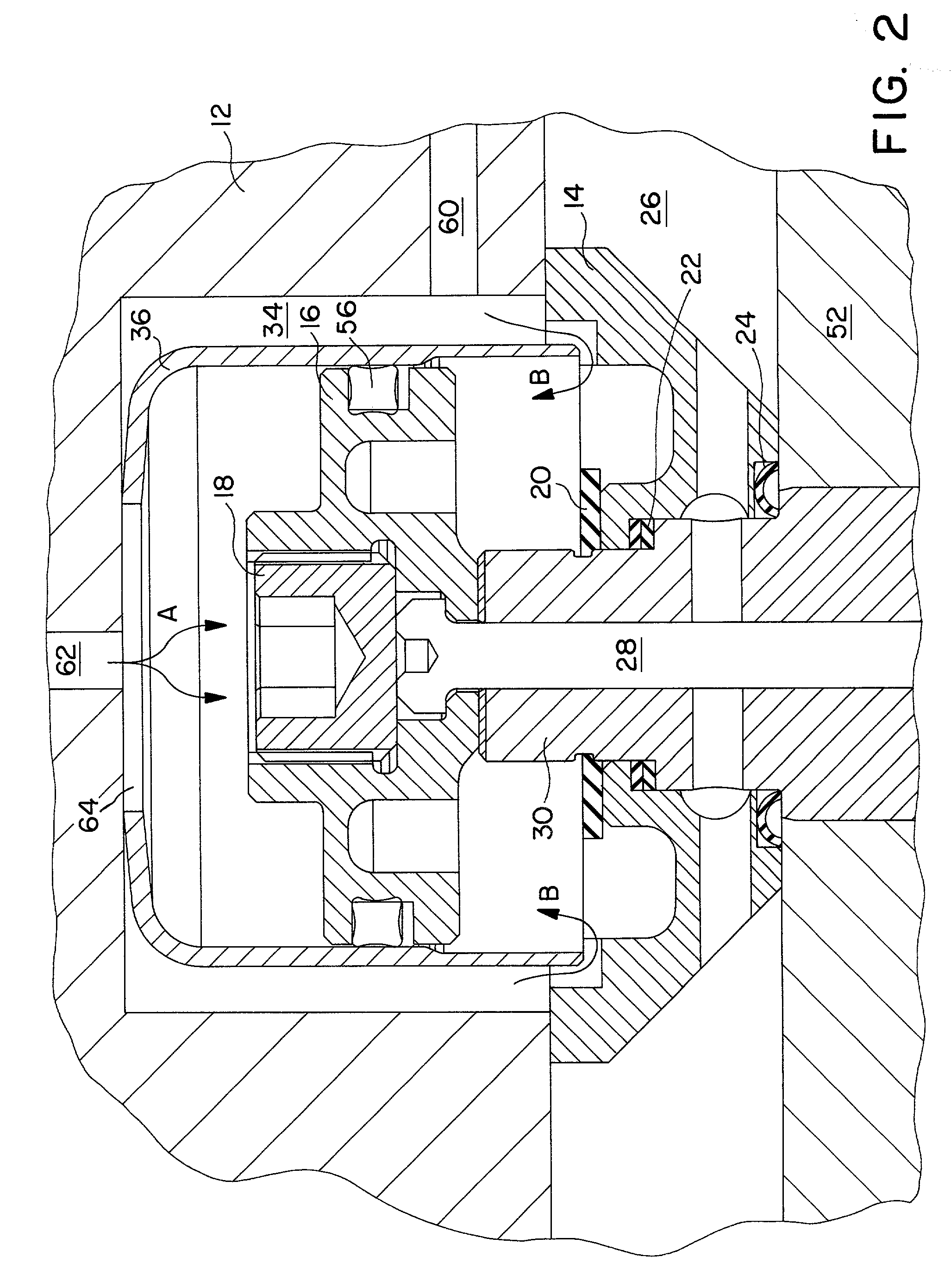
[0018] Referring first to FIG. 3 which shows an injection molding nozzle 100 in accordance with the prior art. A manifold bushing 30 is disposed in a bore of a heated manifold 52. A threaded portion 31 of the manifold bushing protrudes through the manifold and into a cylinder housing 36. A nut 15 is threaded onto the threaded portion 31 of the manifold bushing 30 to affix the cylinder housing to the bushing 30 and the manifold 52.

[0019] An air-operated, double-acting piston 16 is disposed in the cylinder housing 36, and the cylinder housing 36 is disposed in a backing plate aperture 34 formed in a backing plate 12. An elongated valve stem 28 is operatively affixed to the piston 16 and the valve stem 28 extends co-axially through the manifold bushing to a gate orifice 48. The manifold bushing 30 sealingly abuts an elongated nozzle bushing 42, the nozzle bushing 42 being placed in a mold plate cavity 58 and held in fluid communication with the manifold bushing 30 by a mold plate 54. W...


PUM

PropertyMeasurementUnit
temperaturesaaaaaaaaaa
hardenableaaaaaaaaaa
temperatureaaaaaaaaaa

Abstract

An injection molding nozzle is provided having a first sealing member to substantially eliminate the leakage of molten material from around the injection nozzle. A second sealing member is configured to substantially reduce the leakage of a pressurized fluid, such as air, which may be used to open and close a valve stem associated with the injection nozzle.

Description

[0001] 1. Field of the Invention[0002] This invention relates to an injection molding nozzle used in conjunction with an injection molding machine. More specifically, the invention relates to a substantially leak free injection molding nozzle comprising an air operated piston connected to a movable valve stem, with the injection molding nozzle having improved sealing properties therein.[0003] 2. Summary of the Prior Art[0004] An injection molding apparatus may include a heated hot runner manifold for the distribution of a molten material to at least one injection nozzle. Each injection nozzle may be associated with one or more mold cavities, whereby the molten material is transferred to the mold cavity through a gate orifice located at a distal end of the nozzle. During an injection cycle, the gate orifice may be selectably open and closed to start and stop the flow of molten material to the respective mold cavity.[0005] The current state of the art has focused primarily on two type...

Claims


Application Information

Patent Timeline
Patent Type & Authority Applications(United States)
IPC IPC(8): B29C45/28
CPCB29C45/2806B29C2045/2889B29C2045/2762B29C45/281
Inventor BLAIS, PAUL R.
Owner HUSKY INJECTION MOLDING SYST LTD
Why Eureka
Try Eureka