Reciprocating cutting and dilating balloon

a balloon and dilating technology, applied in the field of surgical instruments, can solve the problems of high rate of restnosis in the treatment protocol, and achieve the effect of good axial stiffness and easy navigation

Inactive Publication Date: 2003-07-31
LARY RES & DEV
View PDF13 Cites 68 Cited by
  • Summary
  • Abstract
  • Description
  • Claims
  • Application Information

AI Technical Summary

Benefits of technology

0007] In both the straight blade and curved blade embodiments, the balloon can be shaped wherein a portion of the balloon extends to a greater radial distance than the blades, after the balloon has been inflated. More specifically, the tapered section can extend proximally from the proximal end of each blade. With this cooperation of structure, there will be at least one point on the balloon that is distanced from the longitudinal axis at a distance d with d>r.sub.1 after the balloon has been inflated. This cooperation of structure prevents the blades from cutting into or through the wall of the vascular conduit, while allowing the blades to incise a stenosis that protrudes from the wall of the vascular conduit and into the lumen of the vascular conduit.
0008] To further allow the apparatus to be easily navigated through the vascular conduits of a patient, the catheter can include a flexible coil. In a particular embodiment of the present invention, the flexible coil is positioned proximal to the balloon. In another embodiment of the present invention, the balloon is formed with a cylindrical section that is positioned proximal to the tapered section with at least a portion of the flexible coil positioned inside the balloon. The flexible coil provides lateral flexibility to the apparatus, allowing the blades and at least a portion of the balloon to deflect from the proximal portion of the apparatus during advancement and withdrawal of the apparatus through the vascular conduits. On the other hand, the flexible coil provides good axial stiffness allowing the catheter to be pushed through the vascular conduits. Additionally, the coil is capable of transmitting the axial force required to push the incising blades through a stenosis during an incision.

Problems solved by technology

Dilation of stenoses using standard angioplasty balloons has enjoyed widespread acceptance in the treatment of stenoses, however, this treatment protocol suffers from a high rate of restenosis.

Method used


Image

  • Reciprocating cutting and dilating balloon
  • Reciprocating cutting and dilating balloon
  • Reciprocating cutting and dilating balloon

Examples


Embodiment Construction

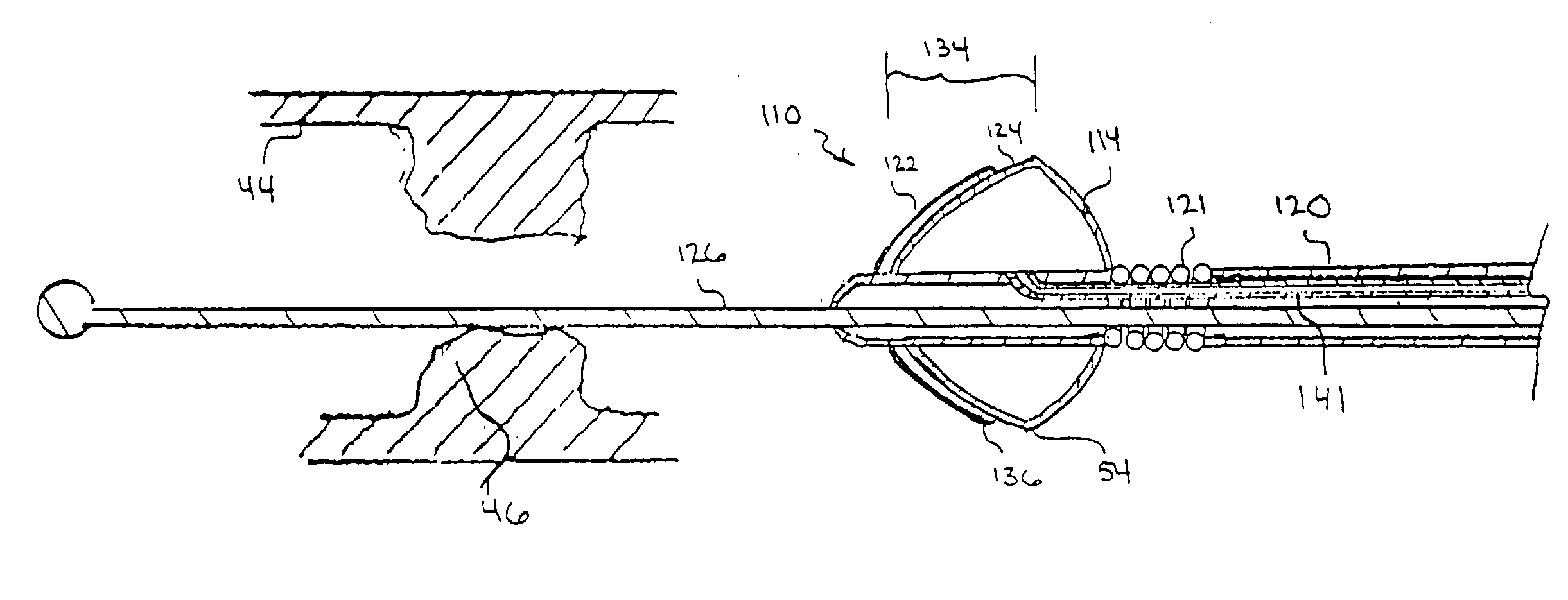
[0004] The present invention is directed to an apparatus for incising and dilating a stenosis within a vascular conduit of a patient. More specifically, the present invention is directed to an apparatus for incising a stenosis with relatively short incising blades that, due to their small size, can be easily guided through the bends and curves of the narrow vascular conduits to the site of the stenosis. For the present invention, the apparatus includes an inflatable balloon that is attached to the distal end of a catheter. The catheter is elongated and defines a longitudinal axis in the direction of elongation. At the distal end of the catheter, the balloon extends axially from a distal end to a proximal end and is formed with an external surface. Also for the present invention, the balloon includes a tapered section that can extend to the distal end of the balloon. More specifically, due to the tapered section, the balloon narrows in the distal direction toward the distal end of th...


PUM


Abstract

An apparatus for incising a stenosis within a vascular conduit of a patient includes an inflatable balloon attached to an elongated catheter that defines a longitudinal axis. The distal end of the balloon includes a tapered section and at least one incising blade is attached to the tapered section. Each incising blade is oriented on the tapered section with the proximal end of the blade radially distanced from the longitudinal axis at a distance r.sub.1 and the distal end of the incising blade radially distanced from the longitudinal axis at a distance r.sub.2. After the balloon has been inflated, each incising blade is oriented with r.sub.1>r.sub.2 to position the incising blades at an angle relative to the axis. This cooperation of structure allows the incising blades to cut an incision into a stenosis during axial advancement of the inflated balloon.

Description

[0001] This application claims the benefit of U.S. Provisional Application No. 60 / 351,893 filed Jan. 25, 2002, U.S. Provisional Application No. 60 / 356,273 filed Feb. 12, 2002 and U.S. Provisional Application No. 60 / 368,009 filed Mar. 27, 2002.FIELD OF THE INVENTION[0002] The present invention relates generally to surgical instruments. More particularly, the present invention pertains to surgical instruments for removing an obstruction in, or for enlarging the orifice of a vascular conduit or connective duct. The present invention is particularly, though not exclusively, useful for incising a stenosis within a vascular conduit and subsequently dilating the incised stenosis to increase bloodflow through the conduit.BACKGROUND OF THE INVENTION[0003] Coronary artery stenosis is primarily due to deposits of cholesterol, calcium and fibrotic tissue. The fibrotic tissue is usually the dominate of the three components and is a tightly composed matrix that, when incised, maintains its integr...

Claims


Application Information

Patent Timeline
Patent Type & Authority Applications(United States)
IPC IPC(8): A61B17/22A61F2/958
CPCA61B17/320725A61M25/1002A61B2017/22061A61B2017/22045
Inventor LARY, BANNING GRAY
Owner LARY RES & DEV
Why Eureka
Try Eureka