Programmable tracking pressure regulator for control of higher pressures in microfluidic circuits

US20030145886A1Inactive Publication Date: 2003-08-07PERSPECTIVE BIOSYST

Image

  • Programmable tracking pressure regulator for control of higher pressures in microfluidic circuits
  • Programmable tracking pressure regulator for control of higher pressures in microfluidic circuits
  • Programmable tracking pressure regulator for control of higher pressures in microfluidic circuits

Examples


Embodiment Construction

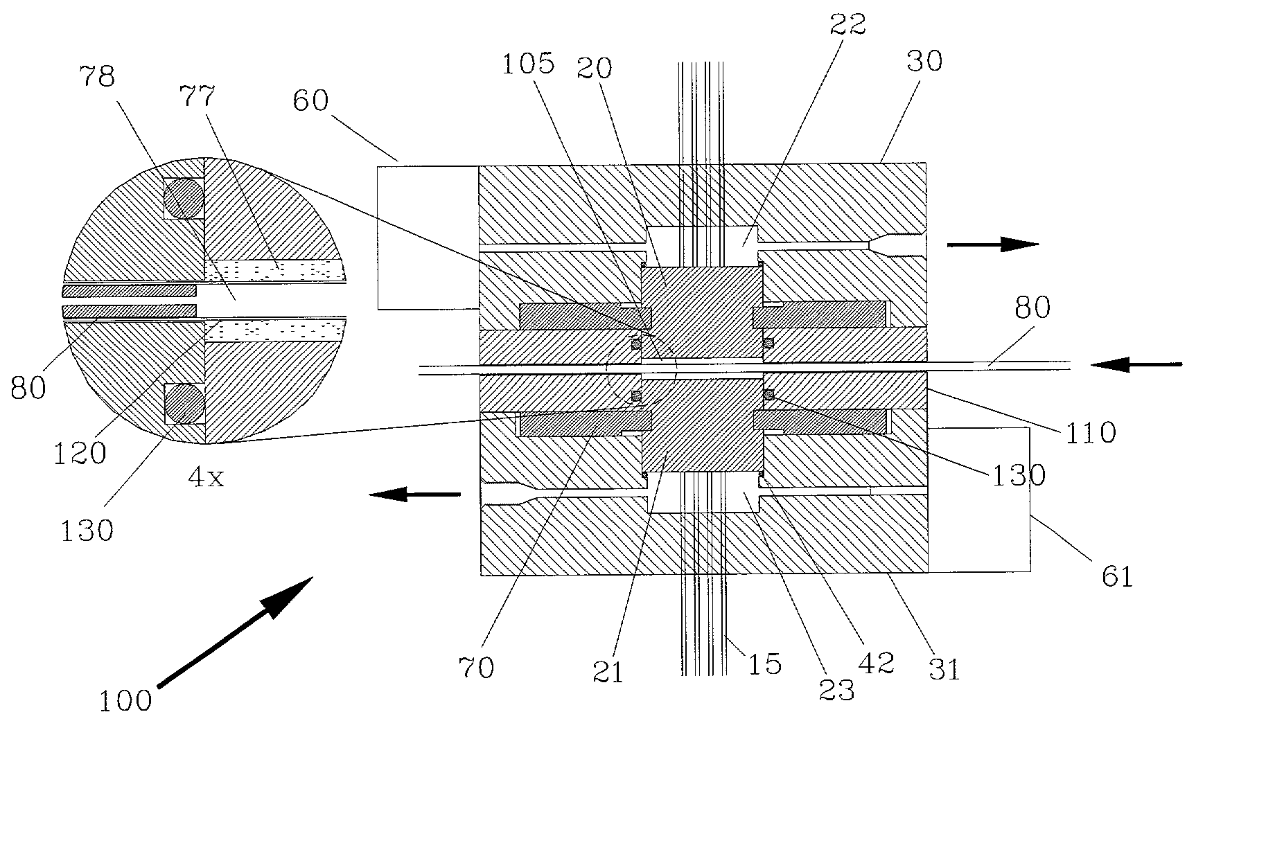
[0032] In order to use capillary gates or "donuts" and capillary forces at higher pressures, especially at much higher pressures typical of high performance liquid chromatography (HPLC), there must be some means for programmable, high-precision pressure control (e.g., .+-.0.01 psi resolution against a background pressure as much as 2000 psi). In addition, the response time must be fast (e.g., within tenths of a second), yet the programmable control must be able to rapidly increase and decrease the pressure, and in some cases, pull the pressure below atmospheric pressure. Furthermore, for HPLC applications, the volume available for measuring the mobile phase pressure must be very small because the composition of the mobile phase is changing. The tracking pressure regulator in accordance with the present invention addresses these issues.

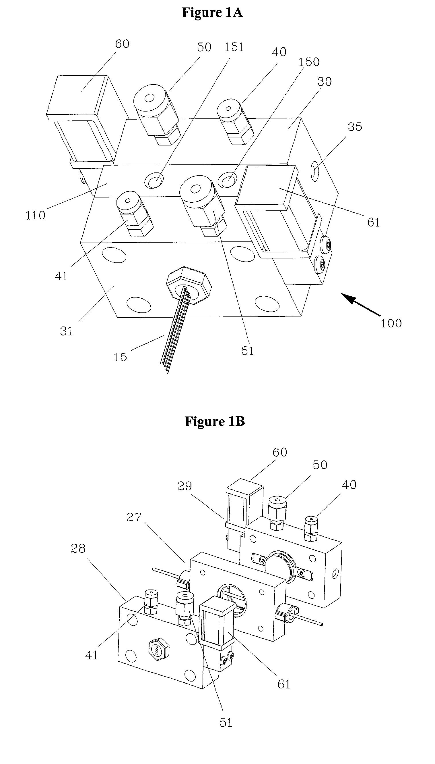
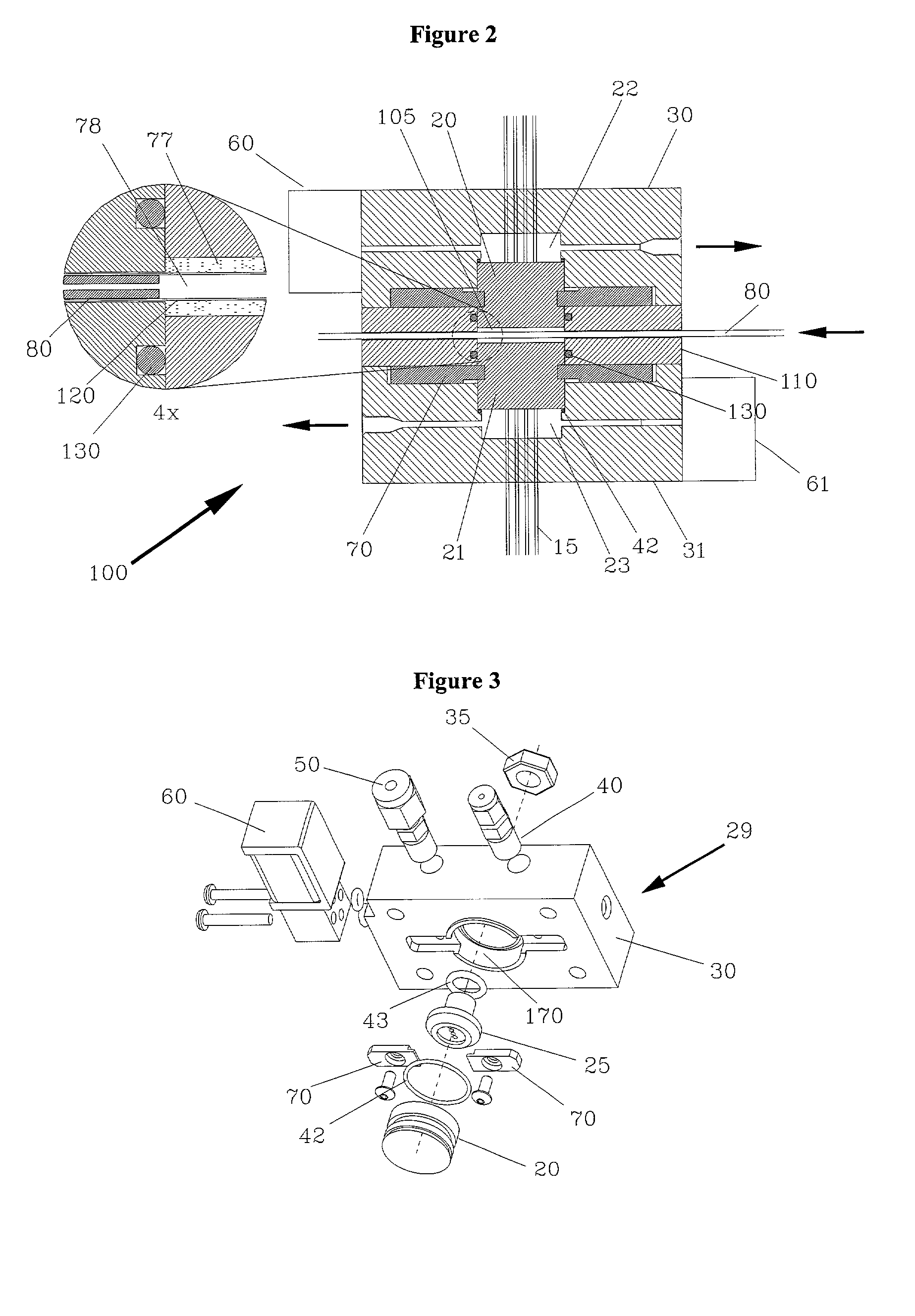
[0033] Turning now to FIG. 1A, there is shown a tracking pressure regulator assembly 100 in accordance with one embodiment of the present invention. T...


PUM


Abstract

Regulator for precision control of pressure based on a means of measuring pressure differentials. More specifically, the present invention provides a pressure control that tracks a relatively high background pressure, and applies a positive or negative offset to create the small pressure differentials that can be utilized to transport fluids within a capillary network. The present invention is also directed to a method of controlling microfluidic elements (such as donut cavities) with a high degree of precision. In high performance liquid chromatography applications, this is accomplished using tracking pressure regulators to measure and respond to the difference between the liquid pump pressure and the regulated pneumatic pressure.

Description

[0001] (a) Field of the Invention[0002] This invention relates to a programmable tracking pressure regulator and method particularly useful for pressure control in apparatus utilizing the formation, control and movement of small volumes of liquid. More particularly, this invention relates to a programmable tracking pressure regulator and method capable of high-precision pressure control in microfluidic networks, even at high operating pressures, for uses such as capillary chromatography.[0003] (b) Description of Prior Art[0004] Fluid transport in microfluidic circuits is normally effected in one of two ways: either by applying pressure differences between selected points in the circuit, or by applying voltage differences between selected points. The application of pressure results in the classical Hagen-Poiseuille laminar flow distribution in capillaries, whereas the application of voltage results in electrokinetic pumping and plug flow. In both cases, however, the control of fluid ...

Claims


Application Information

Patent Timeline
07 Aug 2003
Publication
US20030145886A1
IPC
G01L9/00; G01N30/36; G05D16/20
CPC
G01L9/0001; G05D16/2026; G01N30/36; Y10T137/8326; Y10T137/2076; Y10T137/2529; Y10T137/2514; Y10T137/0396
Inventors
PAUL, CARLTON H.; PRARIA, GUY B.