Tool holder

a tool and tool technology, applied in the field of tool holders, can solve the problems of deteriorating work precision on the machined surface, unavoidable vibration force, and inability to expect effective damping capacity

Inactive Publication Date: 2003-08-07
TOSHIBA MASCH CO LTD
View PDF8 Cites 25 Cited by
  • Summary
  • Abstract
  • Description
  • Claims
  • Application Information

AI Technical Summary

Problems solved by technology

In machine tools, a cutting tool is exposed continuously to cutting resistance forces and so forth during a cutting process for a work piece, so that vibratory forces are unavoidably generated.
Since vibrations generated in the cutting tool have a harmful influence on working precision in machine tools, so that various measures are conventionally taken.
However, it is not possible to expect effective damping capacity by depending on the vibration damping characteristics of the materials themselves of the tools and tool holders lik

Method used


Image

  • Tool holder
  • Tool holder

Examples


Embodiment Construction

[0015] Referring now to the accompanying drawings, a preferred embodiment of a tool holder according to the present invention will be described below.

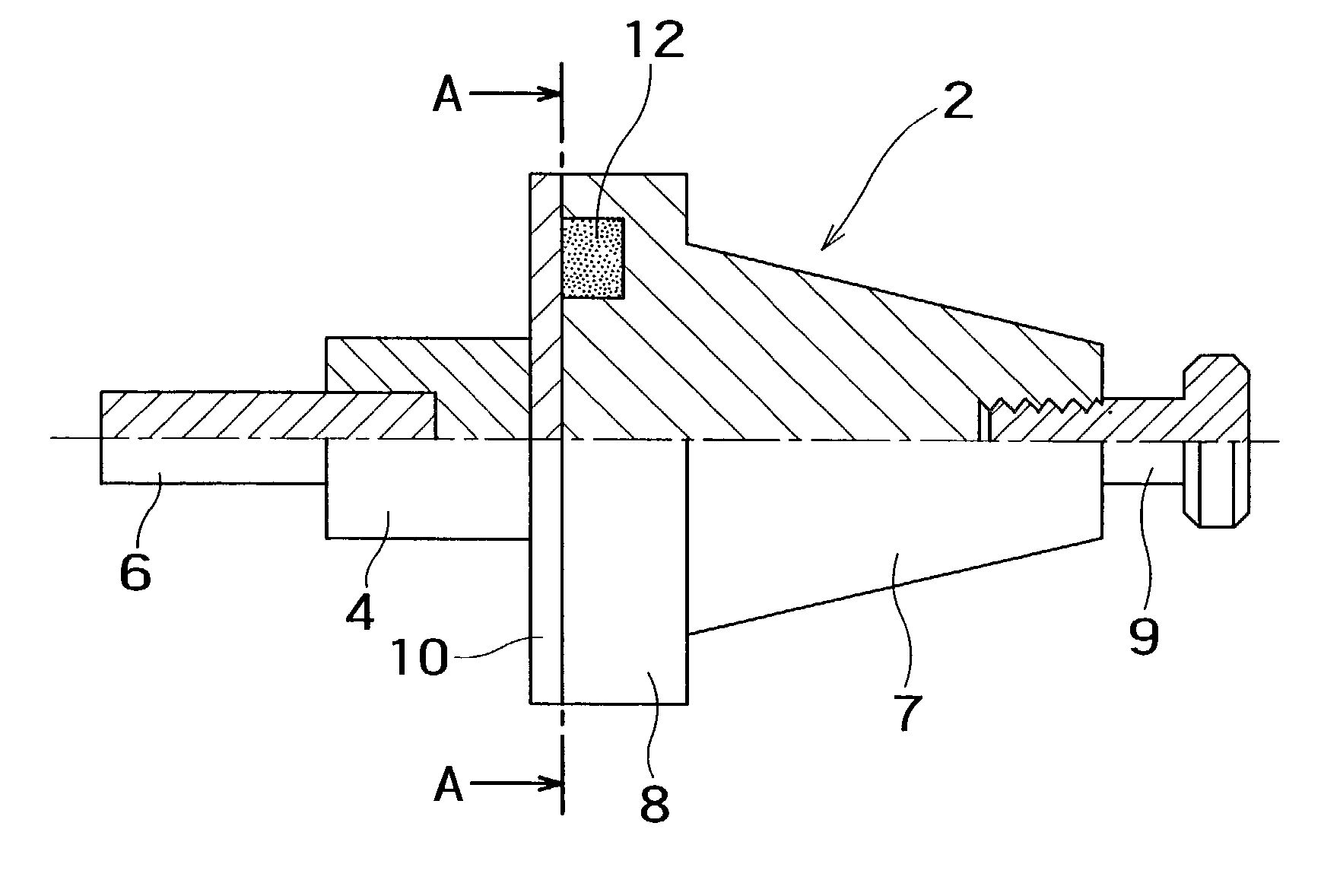
[0016] FIG. 1 shows a tool holder in this preferred embodiment. Reference number 2 denotes an arbor constituting a body of a tool holder. On the front end portion of the arbor 2, a tool mounting portion 4 is provided. A cutting tool 6 is attached into the tool mounting portion 4 to be fixed thereto by means of a bolt (not shown).

[0017] The arbor 2 has a shank portion 7 and a flange portion 8. On the end portion of the shank portion 7, a pull stud 9 is fixed. By inserting the shank portion 7 into a tapered hole open on a spindle and by gripping and pulling the pull stud 9 by means of a collet connected to a draw bar built in a spindle, the arbor 2 can be fixed to the spindle.

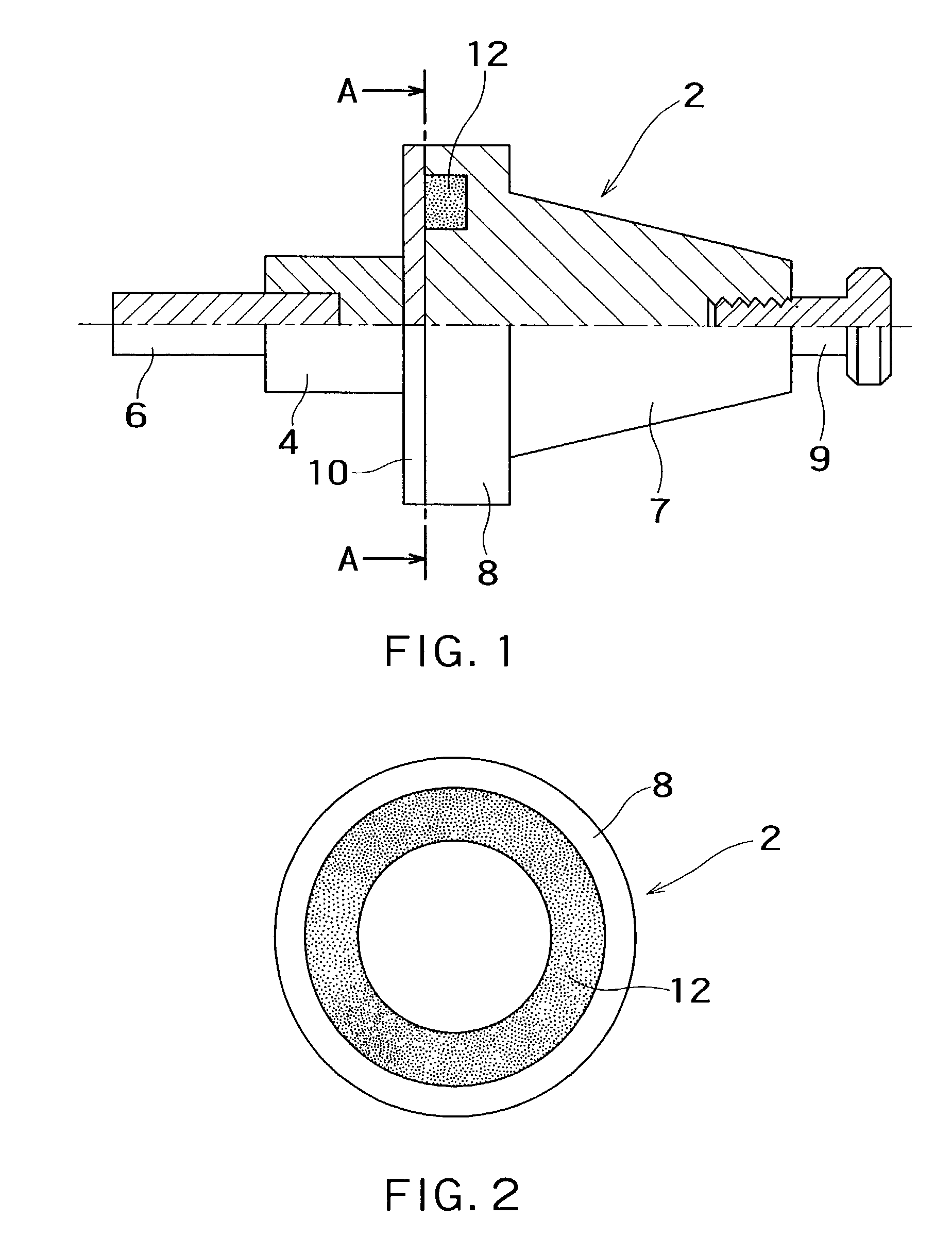
[0018] As shown in FIG. 2, a ring-shaped groove is formed in the end face of the flange portion 8 of the arbor 2. By sealing the ring-shaped groove with a cover mem...


PUM

PropertyMeasurementUnit
Flow rateaaaaaaaaaa
Sizeaaaaaaaaaa
Shapeaaaaaaaaaa

Abstract

A tool holder has a cutter arbor. The cutter arbor has a shank portion detachably mounted on a spindle, and a mechanism for holding a cutting tool. In the cutter arbor portion, a cavity portion is formed. In the cavity portion, a vibration damping material is filled at a filling rate so as to be capable of obtaining predetermined vibration damping characteristics. Thus, it is possible to provide high vibration damping characteristics, effectively damp vibrations during cutting and improve working precision, without using any special materials, such as damping materials, although the tool holder has a usual shape.

Description

[0001] 1. Field of the Invention[0002] The present invention generally relates to a tool holder for attaching a cutting tool to a spindle of a machine tool.[0003] 2. Description of Related Art[0004] In machine tools, a cutting tool is exposed continuously to cutting resistance forces and so forth during a cutting process for a work piece, so that vibratory forces are unavoidably generated. Since vibrations generated in the cutting tool have a harmful influence on working precision in machine tools, so that various measures are conventionally taken.[0005] In general, the cutting tools and tool holders are made of materials having high vibration damping characteristics to inhibit vibrations during cutting processes, and / or tool holders are integrally formed with damping materials by welding or shrinkage fit to inhibit vibrations.[0006] In addition to the enhancement of the vibration damping characteristics of the tool holder itself, it is a well-known art to incorporate a damping mech...

Claims


Application Information

Patent Timeline
IPC IPC(8): B23B31/02B23Q11/00B23B31/117
CPCB23B31/02B23B2231/0292Y10T408/76Y10T409/304312B23B2250/16B23Q11/0032B23B31/117
Inventor KAI, YOSHIAKIENDO, KATSUHITOASANOME, YUTAKAKATOH, KOUICHI
Owner TOSHIBA MASCH CO LTD
Why Eureka
Try Eureka