Battery pack used as power source for portable device

a portable device and battery technology, applied in the field of batteries, can solve the problems of reducing the life of batteries, reducing the service life of batteries,

Inactive Publication Date: 2003-08-14
KOKI HLDG CO LTD
View PDF5 Cites 28 Cited by
  • Summary
  • Abstract
  • Description
  • Claims
  • Application Information

AI Technical Summary

Benefits of technology

[0010] In view of the foregoing, it is an object of the present invention to overcome the above-described problems and provide a battery pack including simple circuitry that improves the life cycle characteristic of the battery.

Problems solved by technology

This heat can reduce the life of the battery.
Also, when the battery is made from a number of cells connected in series, the lower rated capacity cells in the battery can easily become overcharged or over-discharged.
When the battery is repeatedly discharged and charged, the lower rated capacity cell is repeatedly overcharged and over-discharged.
The lower rated capacity cell can leak electrolyte as a result.
In association with this, the capacity of the lower rated capacity cell rapidly decreases, potentially leading to an internal short circuit or disconnection.
These can shorten the life of the battery pack.
This requires complicated control circuitry.
A battery pack that includes such complicated circuitry is too expensive for incorporation into products for every day use.
However, there will be situations where the abnormal condition is not caused by the lower rated capacity cell.
However, there will be situations where such abnormal condition is not caused by the lower rated capacity cell.

Method used


Image

  • Battery pack used as power source for portable device
  • Battery pack used as power source for portable device
  • Battery pack used as power source for portable device

Examples


Embodiment Construction

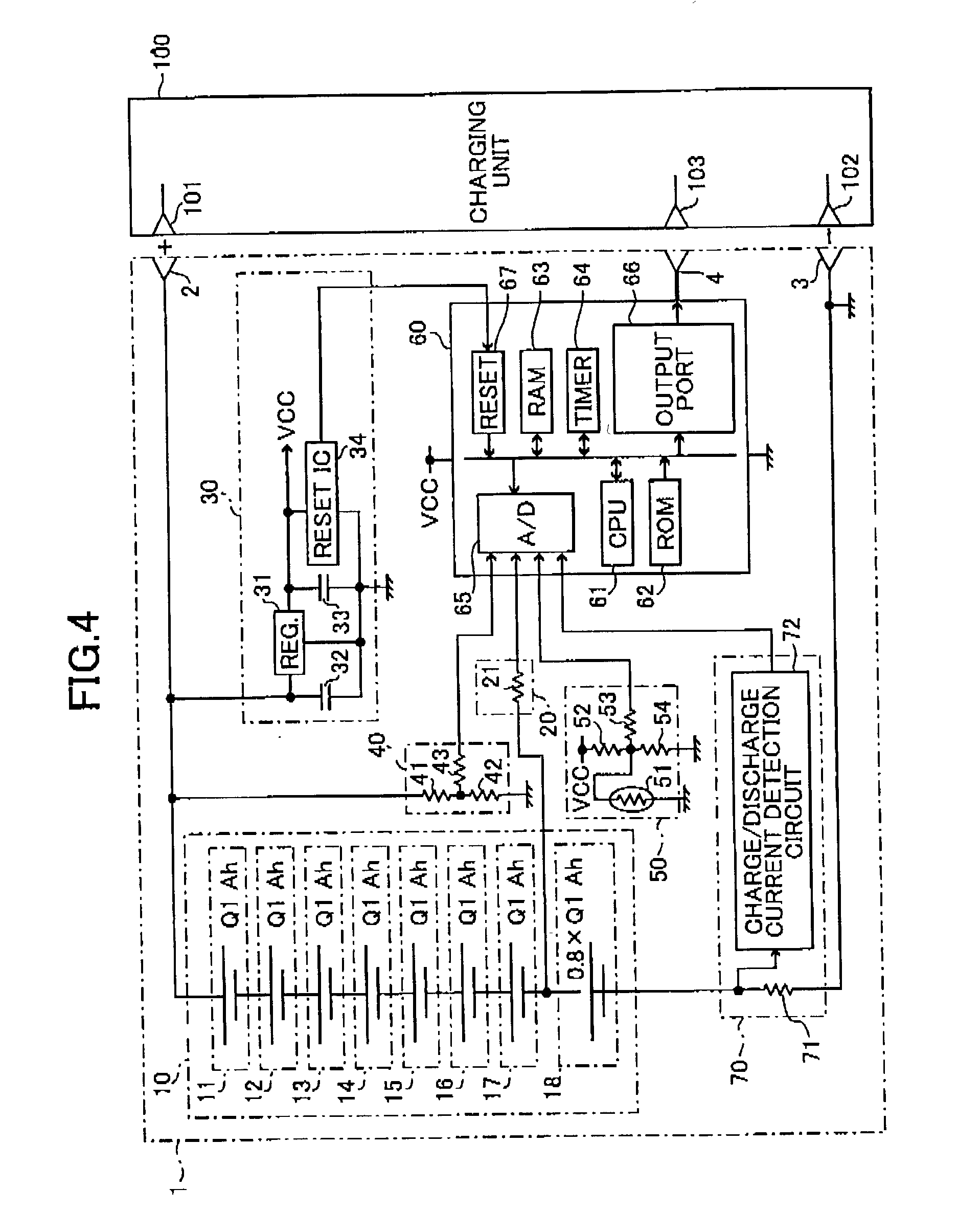
[0035] Next, a battery pack according to an embodiment of the present invention will be described while referring to FIGS. 4 to 6. FIG. 4 is a circuit diagram showing a battery pack 1 connected to a charging unit 100. FIG. 5 is a circuit diagram showing the battery pack 1 connected to a portable device 200.

[0036] As shown in FIG. 4, the battery pack 1 includes a positive terminal 2, a negative terminal 3, a battery 10, a cell voltage detector 20, a constant voltage power source 30, a battery voltage detector 40, a battery temperature detector 50, a microcomputer 60, and a charge / discharge detector 70. The charging unit 100 includes a positive terminal 101, a negative terminal 102, and an information transmission terminal 103. Although not shown in the drawings, the charging unit 100 is connected to a 100V AC power source.

[0037] When the battery pack 1 is connected to the charging unit 11, the positive terminal 2 of the battery pack 1 is connected to the positive terminal 101 of the ...


PUM

PropertyMeasurementUnit
voltageaaaaaaaaaa
voltageaaaaaaaaaa
voltageaaaaaaaaaa

Abstract

A battery pack includes a simple circuitry that improves the life cycle characteristic of the battery. The battery pack includes a plurality of cells connected in series. One of the cells is a lower rated capacity cell having a smaller capacity than the other cells. The lower rated capacity cell is disposed in a first tier of the plurality of cells from a negative terminal of the battery. Temperature and voltage of the lower rated capacity cell are detected to determine whether the lower rated capacity cell has reached the fully charged condition. When the fully charged condition is detected, charging of the battery is stopped. Similarly, based on the temperature and voltage detected, whether the lower rated capacity cell will soon be over-discharged is determined. If so, the use of the battery is stopped.

Description

[0001] 1. Field of the Invention[0002] The present Invention relates to a battery pack including a chargeable battery, such as a nickel-cadmium battery, a nickel-hydrogen battery, or a lithium-ion battery, used as the power source for a portable power tool.[0003] 2. Description of the Related Art[0004] Recently, secondary batteries, such as nickel-cadmium batteries, nickel-hydrogen batteries, and lithium-ion batteries, have increased their capacity and greatly improved charge / discharge performance when charged and discharged with large current. These high-performance secondary batteries are used as the power source of high-load machines, such as cordless power tools (referred to as simply "power tools" hereinafter). Secondary batteries used in power tools are normally in the form of a battery pack that includes a battery made from battery cells connected in series by, for example, a connection plate and used as the power source for high-load devices, enabling the high-load devices t...

Claims


Application Information

Patent Timeline
Patent Type & Authority Applications(United States)
IPC IPC(8): H01M2/10H02J7/00H01M10/42H01M10/44H01M10/48H02J7/02H02J7/04
CPCH01M2/1033H01M10/482H01M10/4264H01M10/425Y02E60/10H01M50/267
Inventor TAKANO, NOBUHIRO
Owner KOKI HLDG CO LTD
Why Eureka
Try Eureka