Track and hold with dual pump circuit

a dual-pump technology, applied in the direction of pulse technique, electric analogue store, instruments, etc., can solve the problems of increasing the cost of manufacturing process, unduly complicating, and the operation of processing techniques under fixed conditions

Inactive Publication Date: 2003-08-14
INTERSIL INC
View PDF2 Cites 22 Cited by
  • Summary
  • Abstract
  • Description
  • Claims
  • Application Information

AI Technical Summary

Problems solved by technology

Such post-processing techniques, however, must be performed on a part-by-part basis thereby unduly complicating and increasing cost of the manufacturing process.
Also, such post-processing techniques operate under fixed conditions and do not correct for inaccuracies or changes due to temperature, aging and / or operating conditions.
Such calibration techniques are limited by quantization and usually limit correction to one-half bit of resolution of the converter itself.
Also, the calibration techniques are incorporated in silicon and thus subject to the same limitations of the target circuitry.

Method used


Image

  • Track and hold with dual pump circuit
  • Track and hold with dual pump circuit
  • Track and hold with dual pump circuit

Examples


Embodiment Construction

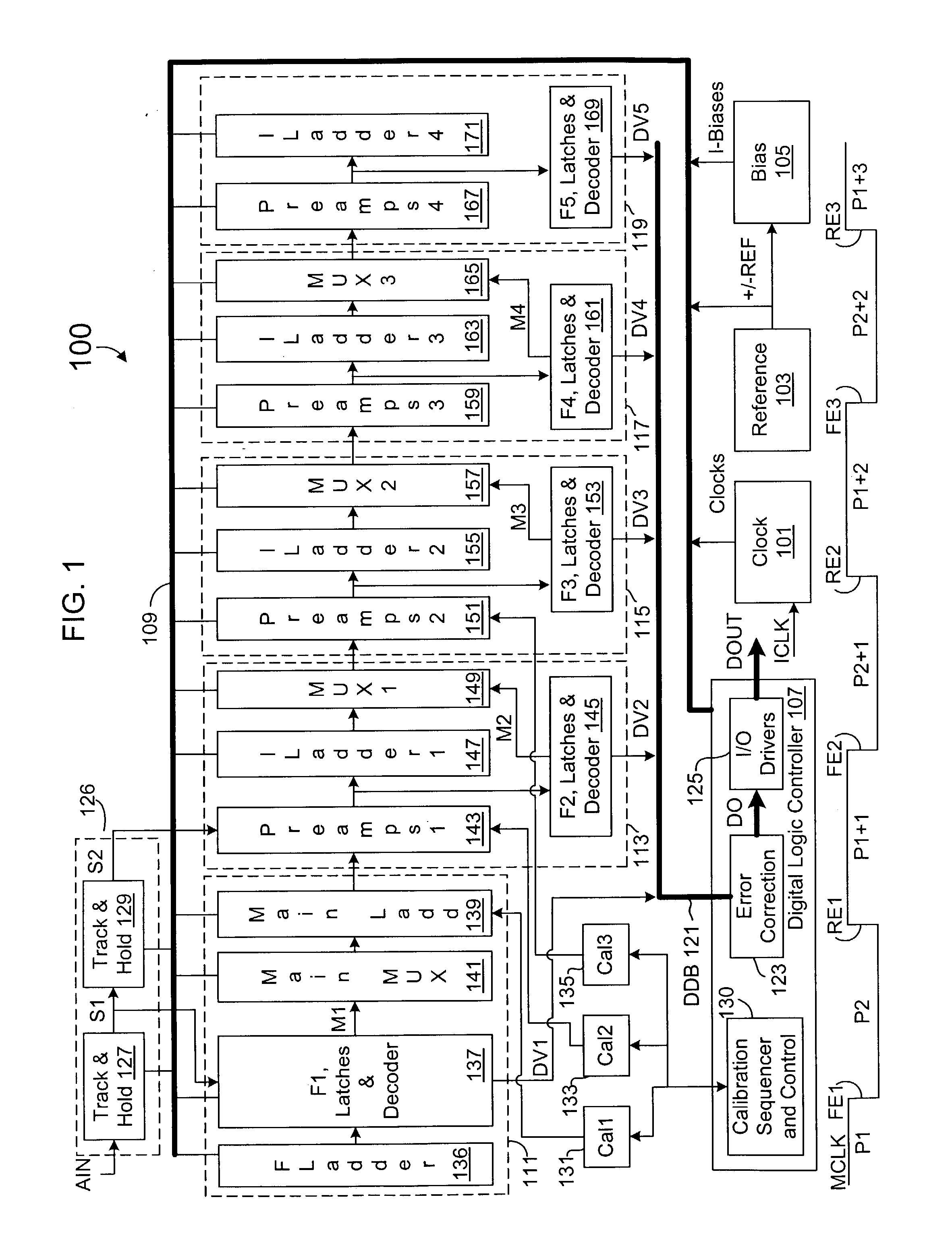
[0017] FIG. 1 is a block diagram of an exemplary 14-bit analog to digital converter (ADC) 100 that is used to illustrate embodiments of the present invention. The ADC 100 includes support circuitry, such as a clock circuit 101, a reference circuit 103, a bias circuit 105 and a digital logic controller 107, all coupled together via a bias / clock bus 109. The clock circuit 101 receives an input clock signal ICLK and generates a plurality of clock signals "Clocks" for providing synchronization of the various components of the ADC 100. The reference circuit 103 generates reference voltage signals +REF and -REF that are sufficiently independent of temperature and power supply variations. The + / -REF signals are provided to the bias circuit 105, which develops a plurality of temperature-independent bias current signals "I-Biases" that provide current biasing for various components of the ADC 100 including preamplifiers within pipelined stages.

[0018] The signals of the bias / clock bus 109 are...


PUM


Abstract

A dual pump circuit including a transmission gate and a dual charge pump. The transmission gate includes a p-channel transistor and an n-channel transistor, each having a control terminal and a pair of current terminals coupled between a dual pump input and a dual pump output. The dual charge pump includes first and second pump circuits, where each pump circuit is coupled to the dual pump input and to a control terminal of a corresponding one of the transmission gate transistors. Each pump circuit is operative to linearize operation of its corresponding transmission gate transistor by maintaining VGS-VT constant. The dual pump circuit is used in a track and hold circuit including at least one dual pump sampling circuit, at least one sampling capacitor, and a control circuit for controlling input signal sampling timing. Each dual pump sampling circuit includes the transmission gate and a dual charge pump.

Description

CROSS-REFERENCE TO RELATED APPLICATION(S)[0001] The present application is based on U.S. Provisional Patent Application entitled "An Analog To Digital Converter", Serial No. 60 / 356,610, filed Feb. 13, 2002, which is hereby incorporated by reference in its entirety. The present application is also a Continuation-In-Part of U.S. patent application entitled "An Analog To Digital Converter Using Subranging And Interpolation", Ser. No. 10 / 097,677, filed Mar. 13, 2002, which is also incorporated herein by reference in its entirety.[0002] The present invention relates to sampling circuits, and more particularly to a high speed track and hold with dual pump circuit that may be used in a sampling circuit to achieve requisite high speed and accuracy.DESCRIPTION OF RELATED ART[0003] Many electronic functions employ sampling circuits for sampling an input signal. The present disclosure, for example, describes an analog to digital converter (ADC) that employs a sample circuit including at least ...

Claims


Application Information

Patent Timeline
Patent Type & Authority Applications(United States)
IPC IPC(8): H03M1/16H03M1/36
CPCH03M1/365H03M1/165
Inventor HAKKARAINEN, J. MIKKOBACRANIA, KANTILALSUNG, ERIC C.CHEN, HSIN-SHUSONG, BANG-SUPSANCHEZ, MARIO
Owner INTERSIL INC
Why Eureka
Try Eureka