Structure of object proximity and position detector

a position detector and object technology, applied in the direction of resistance/reactance/impedence, instruments, pulse techniques, etc., can solve the problems of distortion of signals, ineffective cost, and large chip size of analog circuits, so as to maintain the stability of frequency

Inactive Publication Date: 2006-04-04
HOLYLITE MICROELECTRONICS
View PDF2 Cites 32 Cited by
  • Summary
  • Abstract
  • Description
  • Claims
  • Application Information

AI Technical Summary

Benefits of technology

[0025]FIG. 12 is an object position detector in according to one embodiment of the present invention, which includes an array of sensor plates, two arrays of transmission gate, a sensor os

Problems solved by technology

The chip size of analog circuit is much bigger than that of digital circuit in an integrated circuit, and is not cost effective.
The clock feed-through caused by the parasitic capacitance of analog switches will cause the distortion of the signal.
The interference from RF signal will add to the peak detector directly, and caused the error detection of

Method used


Image

  • Structure of object proximity and position detector
  • Structure of object proximity and position detector
  • Structure of object proximity and position detector

Examples


Embodiment Construction

[0026]The foregoing and other advantages of the invention will be more fully understood with reference to the description of the best embodiment and the drawing as the following description.

[0027]Proximity sensing technology is useful for applications where an object or a finger is in proximity or touches a sensor plates. And a position sensing technology is useful for application where an object or finger position need to be detected in a sensor array.

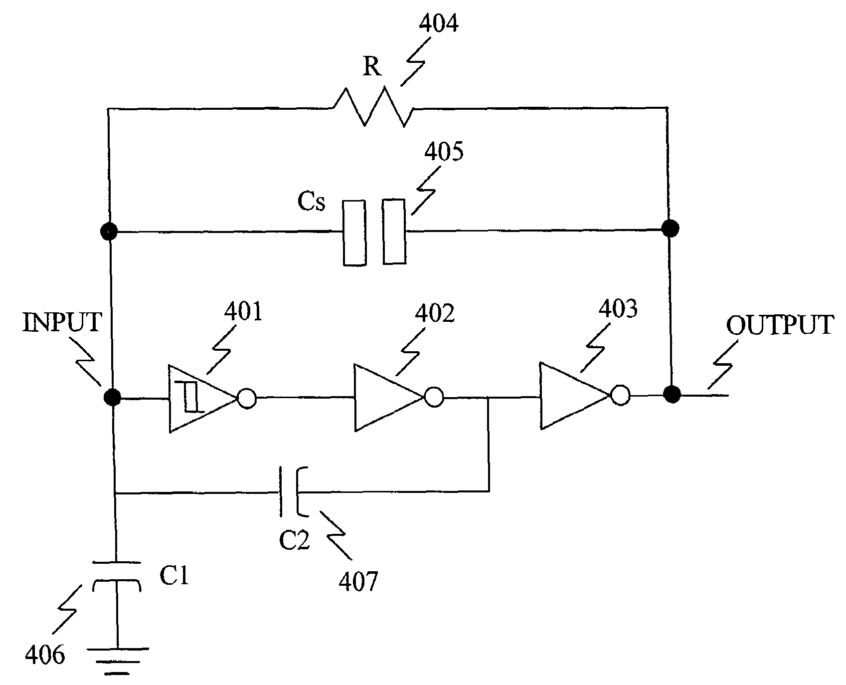
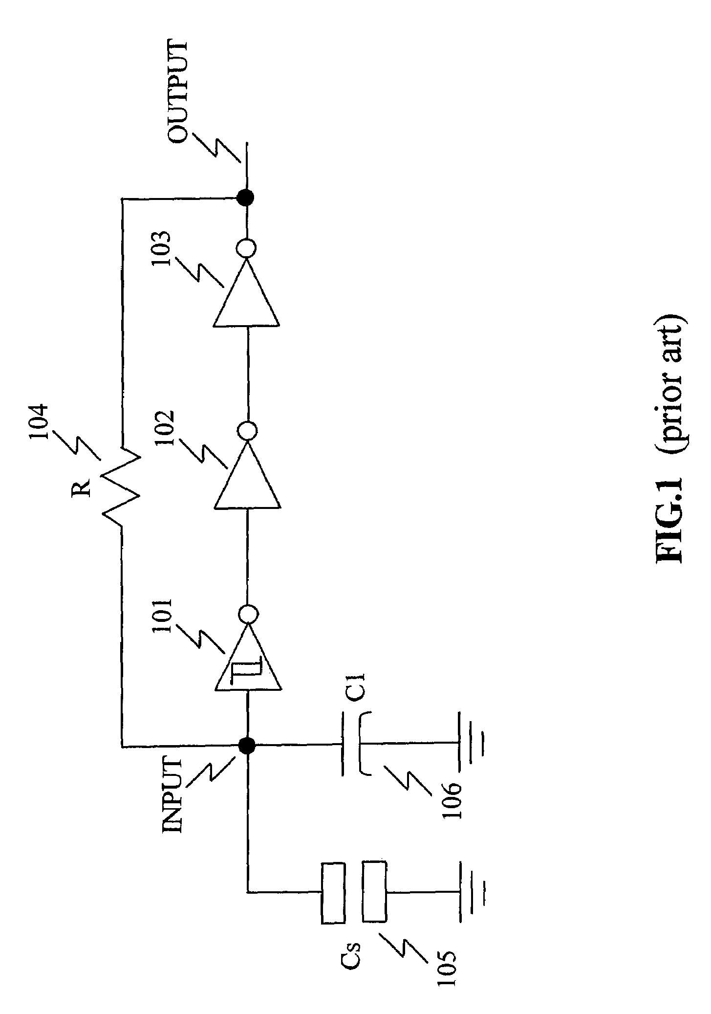
[0028]One embodiment of a proximity sensing circuit or an object position detector of the present invention consists of at least a pair of sensor plates, a sensor oscillator, a time base oscillator, a counter and a microprocessor. In most of application, frequency of the oscillator independent to the variation of process parameters is important. Also high sensitivity is also required. FIG. 3 is an oscillator circuit of the present invention which can compensate the variation of frequency caused by process parameters. And FIG. 4 is the...


PUM


Abstract

The present invention offers an object proximity detector and an object position detector. The variation of frequency of an oscillator is used to detect the proximity of an object to the sensor plates. The dependence of frequency on process parameter is minimized by a compensation capacitor. It is not need to calibrate the product during the manufacture. In order to magnify the sensitivity, the sensor plates are placed in the feedback loop of the oscillator, instead of at the input of the oscillator. The independence of the process parameter and increasing of the sensitivity can be achieved by adding the compensation capacitor and place the sensor plates in the feedback loop at the same time. Multiple transmission gates are connected to the input and the output of the oscillator, and the sensor plates are connected to the transmission gates to form an object position detector.

Description

BACKGROUND OF THE INVENTION[0001]1. Field of the Invention[0002]The present invention relates to an object proximity detector and an object position detector. In particular, the present invention relates to a position detector with multiple transmission gates connected to the input and output of an oscillator and sensor plates connected to the transmission gates.[0003]2. Description of the Related Art[0004]Modern proximity detectors have been used to indicate when one object is close to a detector and to measure how far away one object is from the detector. Capacitive sensors and inductive sensors often are used in proximity detectors. Capacitive proximity sensors translate the variation of capacitance to a binary signal, to determine whether that effective capacitance has been exceeded. The variation of capacitance relates to a distance between an object and the sensor plate / plates. There are a variety of well-known ways of measuring capacitance between the sensor plates. One way i...

Claims


Application Information

Patent Timeline
IPC IPC(8): G01R27/26
CPCG01D5/24H03K17/962G01D5/2405H03K2217/94021
Inventor LIN, SHYUH DER
Owner HOLYLITE MICROELECTRONICS
Why Eureka
Try Eureka