Probe reactive chip, apparatus for analyzing sample and method thereof

a reactive chip and reactive chip technology, applied in the direction of nucleotide libraries, instruments, chemical/physical/physico-chemical processes, etc., can solve the problems of low machined precision of the substrate, misalignment of image files, and inability to accurately detect the position of the chip

Inactive Publication Date: 2003-08-14
NGK INSULATORS LTD
View PDF0 Cites 25 Cited by
  • Summary
  • Abstract
  • Description
  • Claims
  • Application Information

AI Technical Summary

Problems solved by technology

However, the conventional method for analyzing the DNA microarrays through the hybridization step 3 has the following problems that need to be solved.
Namely, these problems include the low machined precision of the substrate 2, which is formed from glass and which configures the DNA microarray, and development of chips/cracks and breakage therein; the misalignment that developments when putting the DNA microarrays on the scanner autoloader or when loading them into the scanner; the accidental error built into the mechanical precision of the autoloader, the scanner, and the like; and further, the micro-dust that attaches to the substrate 2 and inevitably leads to misalignment occurring in the image file of the DNA microarrays to be analyzed.
However, external dimensions of this substrate 2 used to configure the DNA microarrays have low accuracy because of the machined precision, chips/cracks, and breakage of the glass.
Therefore, in practical use, the outside dimension itself of the substrate 2 cannot be used for aligning the DNA microarrays and template

Method used


Image

  • Probe reactive chip, apparatus for analyzing sample and method thereof
  • Probe reactive chip, apparatus for analyzing sample and method thereof
  • Probe reactive chip, apparatus for analyzing sample and method thereof

Examples


Embodiment Construction

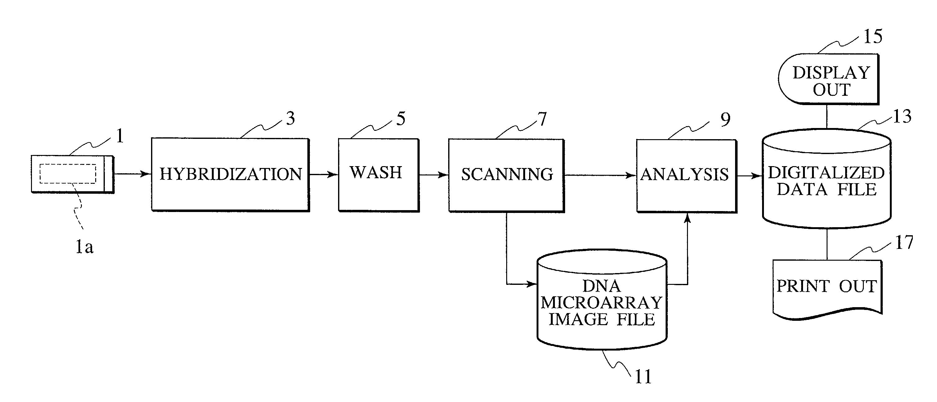
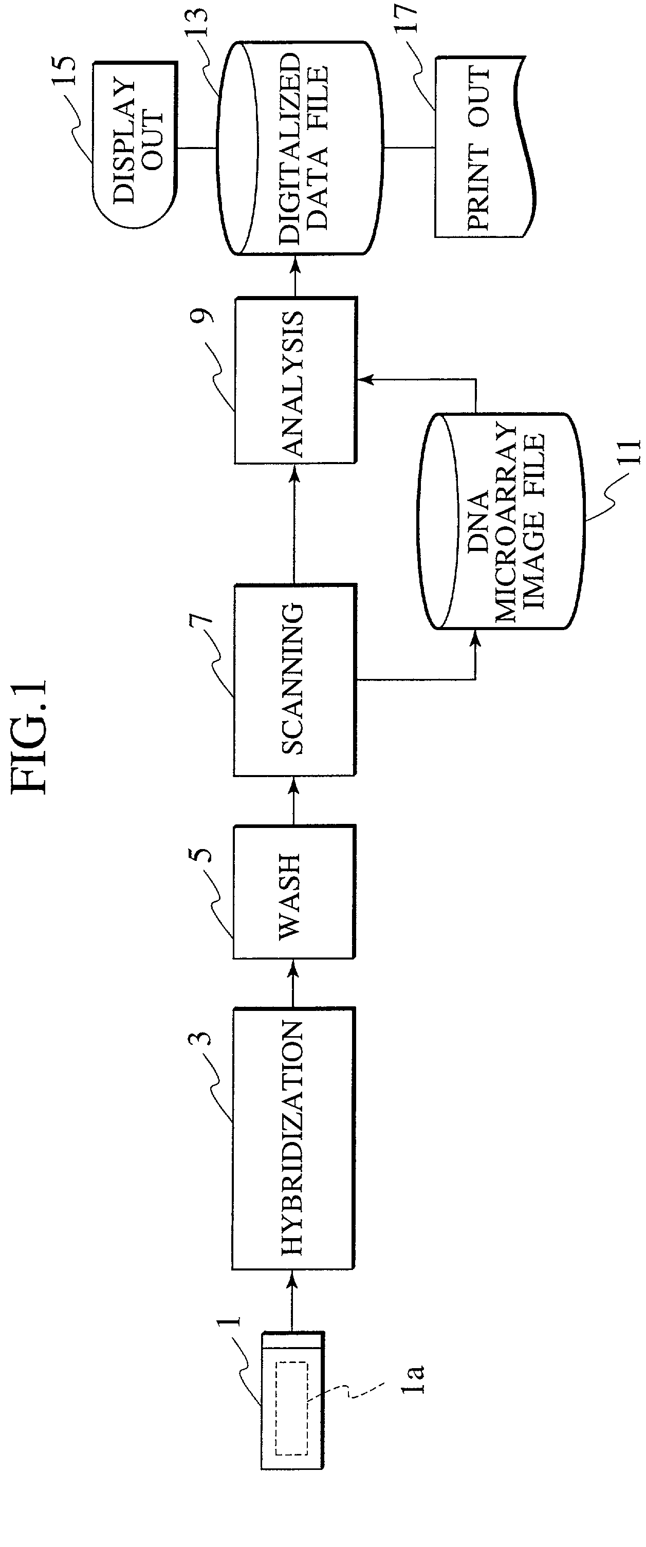
[0105] Hereafter, a DNA microarray (DNA chip), a sample analysis apparatus, and a method thereof are described in detail, while referencing FIGS. 4 through 33.

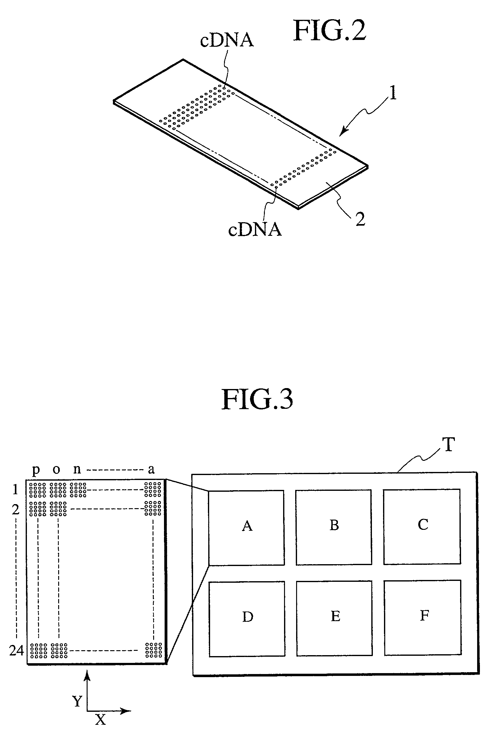
[0106] In this embodiment, detection area alignment processing and misalignment correction processing are implemented on a DNA microarray image file, providing a reference mark, which is used for detection area alignment of a DNA microarray image file, is provided upon the DNA microarray substrate to be analyzed, and in addition, a reference pattern, which is utilized for the alignment processing mentioned above as well as misalignment correction processing, is deployed within a block comprising the spot area of the DNA microarrays. In addition, in this embodiment, the alignment processing is performed in a plurality of phases: by DNA microarray, by spot, and by block.

[0107] FIG. 4 is a block diagram illustrating the overall configuration of a sample analysis system according to an embodiment of the present invention.

[0108] As...


PUM


Abstract

Technology is disclosed for highly accurate automated execution of processing for alignment of a detection area to a DNA microarray image file and processing for quantitative determination of success/failure of the alignment during DNA microarray analysis. A probe reactive chip used for the technology comprises a substrate; a spot area wherein spots for fixing a probe capable of specifically reacting to a sample marked so as to be optically detectable are formed in a matrix on a surface of the substrate; and a reference pattern area, which is arranged within the spot area or approximate to the spot area, and comprises a plurality of different alignment marks in order to correct misalignment of the spot during analysis of the sample on the surface of the substrate.

Description

[0001] 1. Field of the Invention[0002] The present invention relates to a method for analyzing a DNA microarray and a sample using the DNA microarray. More specifically, it relates to technology for improving accuracy and automating image analysis of the DNA microarrays by performing the alignment of a detection area defined by an analyzing tool and image correction relative to images of the DNA microarrays read via a scanner, in the image analysis of the DNA microarrays after hybridization.[0003] 2. Description of the Related Art[0004] In recent years, genetic analysis has been implemented using DNA microarrays.[0005] In this specification, DNA microarrays or DNA chips refer to the spotting of DNA in a grid-like pattern upon an array substrate comprising glass or the like. Upon the DNA microarrays, DNA is spotted as probes capable of specifically reacting to marked DNA samples.[0006] After an unknown DNA sample to be analyzed is run in onto the DNA microarrays and the sample has be...

Claims


Application Information

Patent Timeline
IPC IPC(8): B01J19/00C40B40/06G01N35/00G01N35/04
CPCB01J19/0046B01J2219/00529B01J2219/0054B01J2219/00576B01J2219/00677B01J2219/00689G01N2035/0494B01J2219/00695B01J2219/00702B01J2219/00722B82Y30/00C40B40/06G01N2035/00158B01J2219/00693
Inventor KIRA, SHIGEKIYAMADA, KAZUNARIHIROTA, TOSHIKAZUYOSHIDA, YASUKO
Owner NGK INSULATORS LTD
Why Eureka
Try Eureka