Method of reinforcing a mechanical microstructure

Inactive Publication Date: 2003-09-04
COMMISSARIAT A LENERGIE ATOMIQUE ET AUX ENERGIES ALTERNATIVES
View PDF3 Cites 11 Cited by
  • Summary
  • Abstract
  • Description
  • Claims
  • Application Information

AI Technical Summary

Benefits of technology

0017] first, thanks to the localized character of the abutment stud, the recess in vertical alignment with the first layer is at a predetermined distance sufficient to prevent the formation of stray capacitances between the first layer and the second layer, and
0018] second, because o

Problems solved by technology

During this development process, the inventors were first confronted with the problem of stray capacitances appearing between the active portion and the cap.
During their research, they found that deterioration could occur, especially at the moment of producing the e

Method used


Image

  • Method of reinforcing a mechanical microstructure
  • Method of reinforcing a mechanical microstructure
  • Method of reinforcing a mechanical microstructure

Examples


Embodiment Construction

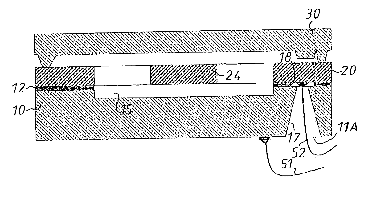
[0032] FIG. 1 shows a geophone microstructure approaching completion and having at least the following three main portions: a central layer 20 including a mobile mass 24 sensitive to the accelerations to be detected by the geophone, a support layer 10 that carries the central portion, and a top layer 30, which covers the central layer and defines with the support layer 10, an enclosure that can be evacuated if necessary.

[0033] In a preferred embodiment, each layer is made from a silicon substrate.

[0034] One or more of the substrates can instead be made from a different material.

[0035] Each substrate can initially have the same characteristics and in particular the same thickness, for example 450 .mu.m.

[0036] In a preferred embodiment, the top layer 30 corresponding to the top portion is 300 .mu.m thick.

[0037] However, since, in a geophone, the central layer must in principle have a much smaller final thickness (it is referred to as a thin layer), it is necessary, prior to the specif...


PUM

PropertyMeasurementUnit
Microstructureaaaaaaaaaa
Areaaaaaaaaaaa
Distanceaaaaaaaaaa

Abstract

A mechanical microstructure including a deformable first layer overhanging a second layer and defining a cavity set back from an external face of the deformable first layer and having an abutment stud projecting into the cavity, in which a wire is connected to a portion of an internal face of the deformable first layer. The portion of the first layer is opposite a bottom area of the cavity into which the abutment stud projects, but the abutment stud remains at a distance from the deformable first layer. A method of producing the mechanical microstructure is also disclosed.

Description

[0001] This application claims priority under 35 U.S.C. .sctn.119 to French patent application No. 0117014, filed Dec. 28, 2001.[0002] The present invention The present invention relates to method of producing a mechanical microstructure and to a mechanical microstructure having an electrically active portion. This kind of microstructure can advantageously constitute sensor, for example a pressure sensor, or an actuator, for example an optical microsystem (MOEMS). It has a preferred, but not exclusive, application in the field of inertial components, such as accelerometers.[0003] The commonly assigned French patent FR 2,558,263 discloses the fabrication of micromechanical devices by microelectronic techniques. These methods produce a microstructure, which is defined as a mechanical structure produced using microelectronic techniques, that is to say collective processing of substrates by deposition, etching, photolithography, etc.[0004] In the case of accelerometers, the electrically...

Claims


Application Information

Patent Timeline
IPC IPC(8): B81B3/00B81B7/00G01P15/125B81C1/00G01P15/08H01L29/84
CPCB81B7/0012G01P2015/0814B81C1/00896
Inventor CAPLET, STEPHANE
Owner COMMISSARIAT A LENERGIE ATOMIQUE ET AUX ENERGIES ALTERNATIVES
Why Eureka
Try Eureka