Foil bearing and spindle device using the same

a technology of oil bearing and spindle, applied in the direction of rotary bearings, shafts and bearings, electrostatic spraying apparatus, etc., can solve the problems of reducing life, considerable unbalance, and considerable unbalan

Inactive Publication Date: 2003-09-11
NTN CORP
View PDF5 Cites 74 Cited by
  • Summary
  • Abstract
  • Description
  • Claims
  • Application Information

AI Technical Summary

Problems solved by technology

However, the use of the rolling bearings have brought about problems associated with the lifetime which often decreased as a result of high speed rotation of the rotary shaft within an atmosphere rich of solvent gases and also with contamination of the painting material in contact with a lubricating oil leaking from the bearings.
While the rotary atomizer requires a frequent replacement of the atomizer head, a frictional wear of a mount used on the rotary shaft for supporting the atomizer head and/or a deformation of the atomizer head tend to bring about a considerable unbalance.
Also, even an uneven deposition of a liquid medium to be treated and subsequent solidification thereof while being deposited also brings about a considerable unbalance.
For these reasons, the spindle used in the rotary atomizer have to endure such a considerable unbalance while it rotates at a high speed.
However, with the conventional spindle devices shown respectively in FIGS. 16 and 17, the spindle is unable to withstand against an exciting force resulting from the unbalance and the spindle will eventually fail to rotate as a result of contact of the rotary shaft with the bearing surface.
In such case, if the spindle is heavy, the articulated robot of a bulky size would be required, posing a problem associated with the space for installation and the cost.
By these reasons, it is difficult to reduce the wall thickness of the various component parts in an attempt to reduce the weight of the spindle device.
Other than the failure of the rotary shaft to rotate properly as a result of contact with the bearing surface, failure of the rotary shaft to rotate properly may occur when the liquid medium to be treated ingresses inside the spindle.
With the conventional spindle device, once the failure occurs, the rotary shaft failing to rotate properly has to be removed from the spindle device and then to be submitted to the manufacturer for repair, resulting in both increase of the cost for repair and waste of a substantial amount of time.
Where the line is desired to be operated while the rotary shaft is submitted to the manufacturer for repair, an extra spindle must be prepared for replacement with the rotary shaft and, therefore, maintenance is costly in this respect.
In the case of the spindle utilizing the tilting pad type bearings shown in FIG. 17, in order to secure a predetermined floating characteristic, the radius of curvature of the bearing sur

Method used


Image

  • Foil bearing and spindle device using the same
  • Foil bearing and spindle device using the same
  • Foil bearing and spindle device using the same

Examples


first embodiment

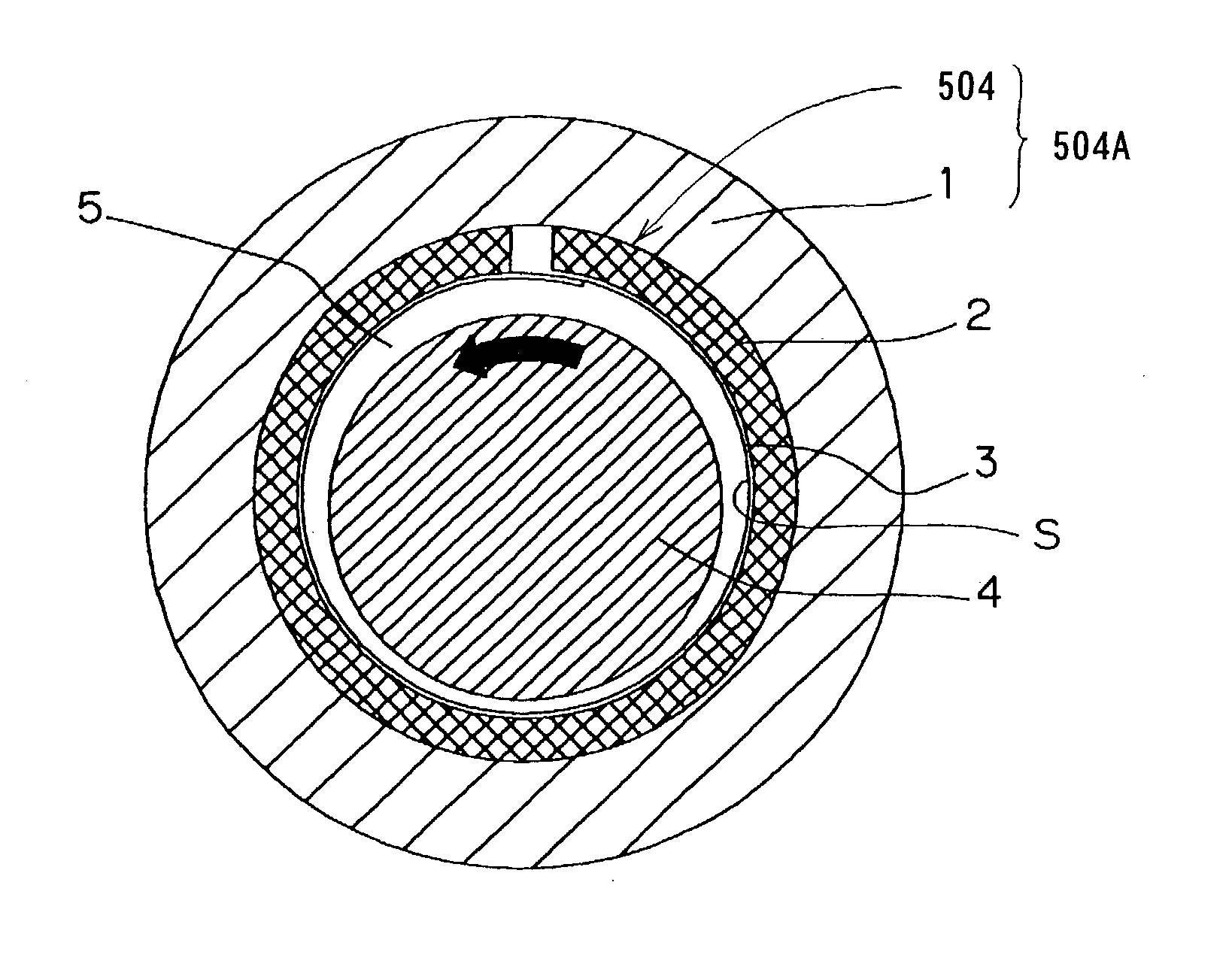
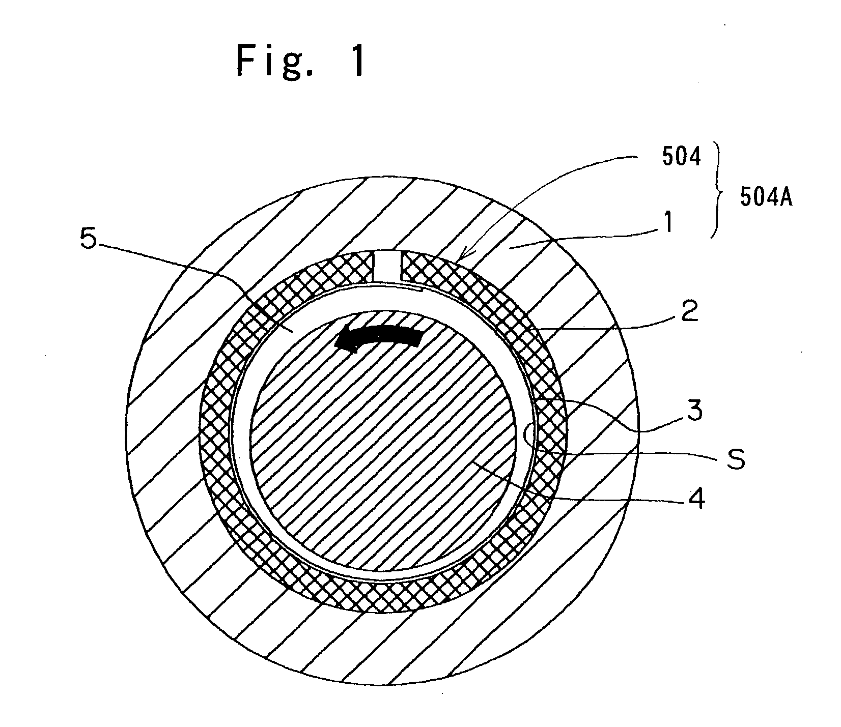
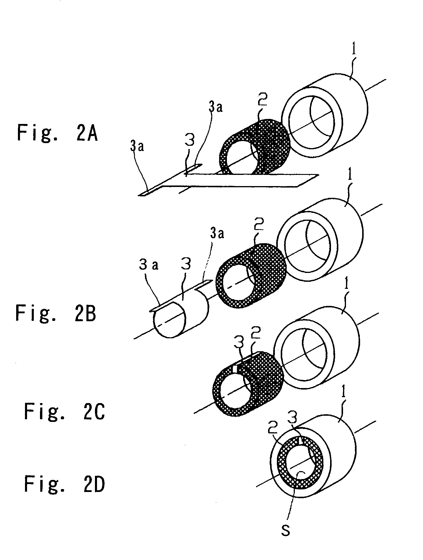
[0073] With reference to FIGS. 1 and 2D, a foil bearing according to a first preferred embodiment of the present invention will be described. It is to be noted that the first embodiment shown therein will be described as applied to a sliding bearing of a radial type, that is, a journal bearing. The illustrated foil bearing includes an elastic member 2 formed by pressing a generally wire net, and a bearing foil 3 in the form of a metal foil. The elastic member 2 is shaped to assume a cylindrical configuration by a press work used in pressing the metal net. The metal net referred to above is prepared from thin metal wires. The wire net may be of a structure wherein wires are so braided in either a two-dimensional band or a three-dimensional shape that they will not be naturally disentangled. Specifically, the wires forming the wire net may be so braided or so knitted in a manner similar to a textile fabric, or so merely entangled that they will not come loose.

[0074] As shown in FIGS. ...

second embodiment

[0085] Even in this second embodiment, this radial bearing 504 and the bearing housing 1 altogether define a bearing unit 504A.

[0086] Referring to FIG. 5, a third preferred embodiment of the present invention will be described with the present invention applied to the journal bearing. In this embodiment shown in FIG. 5, the elastic member 2 is corrugated to have hills and dales that alternate one after another in a direction circumferentially thereof. In the assembled condition, the hills and dales of the elastic member 2 are held in contact with the inner peripheral surface of the bearing housing 1 and the bearing foil 3, and vice versa. As a matter of course, the elastic member 2 prior to being connected together with the bearing foil 3 is prepared from the wire net as hereinbefore described and is corrugated in any known manner. The use of the corrugated elastic member 2 is effective to allow the rigidity of support of the bearing foil 3 to be set to a wide range. It is to be not...


PUM


Abstract

A foil bearing is provided, which is simple in structure, has a large load capacity and a large damping capability and can therefore allow a rotary shaft having a large unbalance as compared with the conventional bearing to be driven stably at a high speed. A spindle device utilizing such foil bearing is also provided, which is designed to increase the permissible amount of unbalance and also to have a light-weight feature. Each of the foil bearings 504 and 505 includes an elastic member 2 prepared from a wire net formed by braiding wires, and a thin bearing foil 3 supported by the elastic member 2 and defining an elastic bearing surface S. The respective foil bearing 504 and 505 is used at least as a radial bearing 504 in the spindle device including a rotary shaft 4 having a head mount 501a, on which an atomizer head is mounted, and the radial and thrust bearings 504 and 505 for rotatably supporting the rotary shaft 4.

Description

[0001] 1. Field of the Invention[0002] The present invention generally relates to a foil bearing which is one of the fluid bearings used in various machines and equipments and, more particularly, to the foil bearing suitable for supporting a rotary shaft of a kind used in machines and equipments requiring a high speed rotation of the rotary shaft, such as, in particular, a turbo machines including a turbo compressor, an expansion turbine and a gas turbine, and an electrostatic painting device of a rotary atomizing type, and also to a spindle device using the foil bearing and having the rotary shaft on which an atomizer head is mounted, for example, a high speed spindle device for use in a rotary atomizer for atomizing a liquid medium by the effect of a centrifugal force.[0003] 2. Description of the Prior Art[0004] The rotary atomizer for atomizing, by the effect of a centrifugal force, a liquid medium supplied to a disk-shaped atomizer head then rotating at high speeds is generally ...

Claims


Application Information

Patent Timeline
IPC IPC(8): B05B5/04B05B7/08F16C17/12F16C35/02
CPCB05B5/0415B05B7/0815F16C35/02F16C17/042F16C17/024B05B5/0426F16C27/02F16C43/02
Inventor NISHIJIMA, HIDEHIKOFUJIKAWA, YOSHIO
Owner NTN CORP
Why Eureka
Try Eureka