Projector

a projector and projector technology, applied in the field of projectors, can solve the problems of hindering the size reduction of the projector, affecting the size of the projector, and the driving block of the light source likely to be a noise source of electromagnetic failure,

Inactive Publication Date: 2003-09-18
SEIKO EPSON CORP
View PDF6 Cites 17 Cited by
  • Summary
  • Abstract
  • Description
  • Claims
  • Application Information

AI Technical Summary

Benefits of technology

[0010] Recently, in order to improve performance of a projector, the luminance of light source is enhanced, and the electric power supplied from a light source driving block to the light source increases in accordance therewith, so that electromagnetic wave causing electromagnetic failure is likely to be radiated from the light source driving block.
[0028] Further, since the light source driving block is covered with a tube-shaped shield member, even when electromagnetic wave radiated by the light source driving block increases in accordance with enhancing the luminance of the light source, the electromagnetic wave can be shielded so as not to be leaked toward the outside, thus avoiding electromagnetic interference on, especially, the other electronics located outside of the projector.

Problems solved by technology

However, since a light source driving block including the light source driving circuit has a transforming coil for transforming the voltage from an external power source into a predetermined voltage, a capacitor for storing electric power, resistor etc., the light source driving block is likely to be a noise source of electromagnetic failure, which especially influences on a control block for controlling an electric optical device.
However, such arrangement hinders the size reduction of the projector.
Especially, since circuit elements such as IC and LSI are highly densely installed on the control block for controlling an electric optical device, the control block is likely to be influenced by noise caused by the electromagnetic wave radiated from the light source driving block.
When outside noise is received by the signal processing circuit, the image is distorted and vivid image cannot be displayed.

Method used


Image

  • Projector
  • Projector
  • Projector

Examples


Embodiment Construction

)

[0041] An embodiment of the present invention will be described below with reference to the attached drawings.

[0042] [1. Primary Arrangement of Projector]

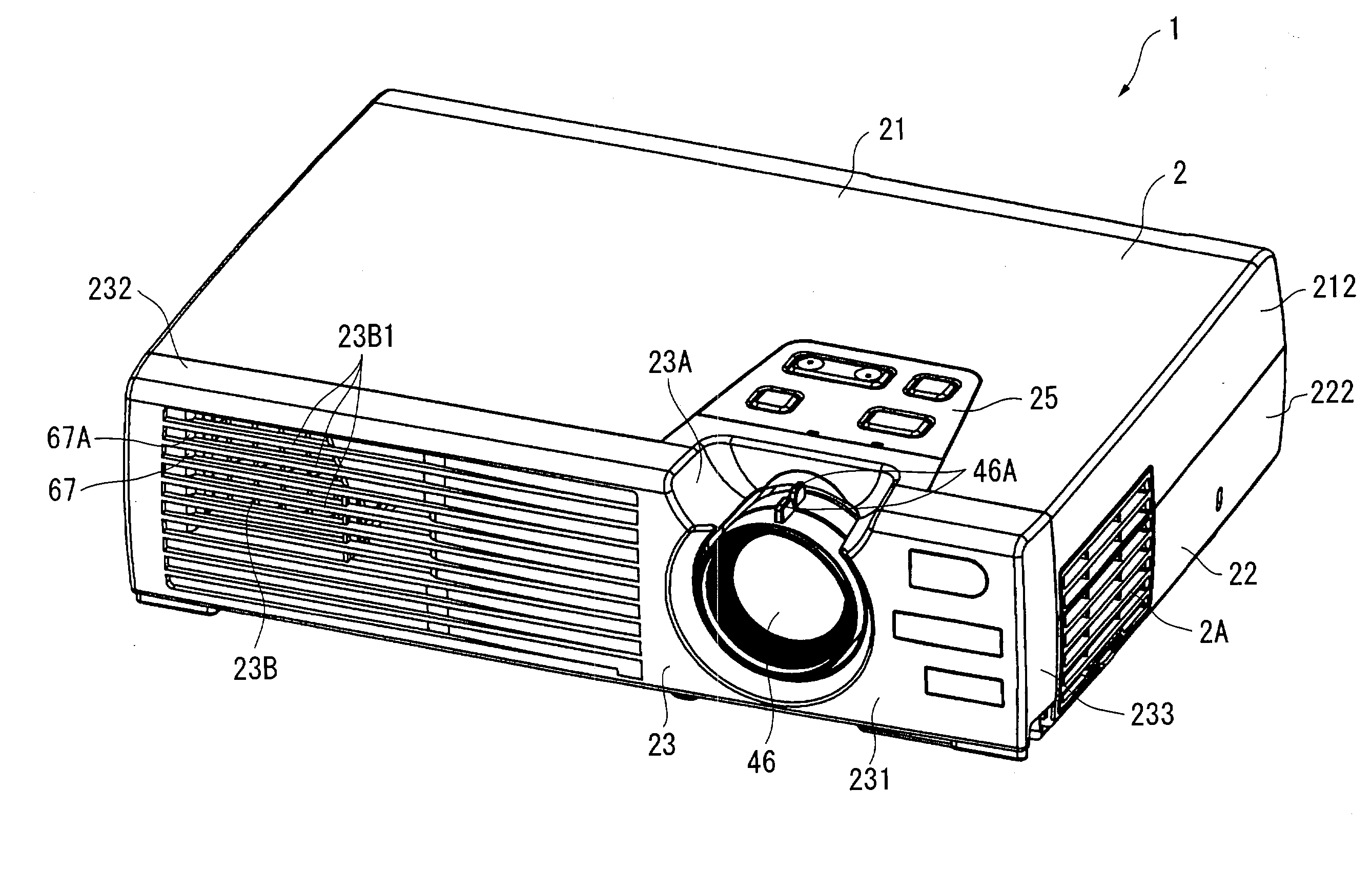
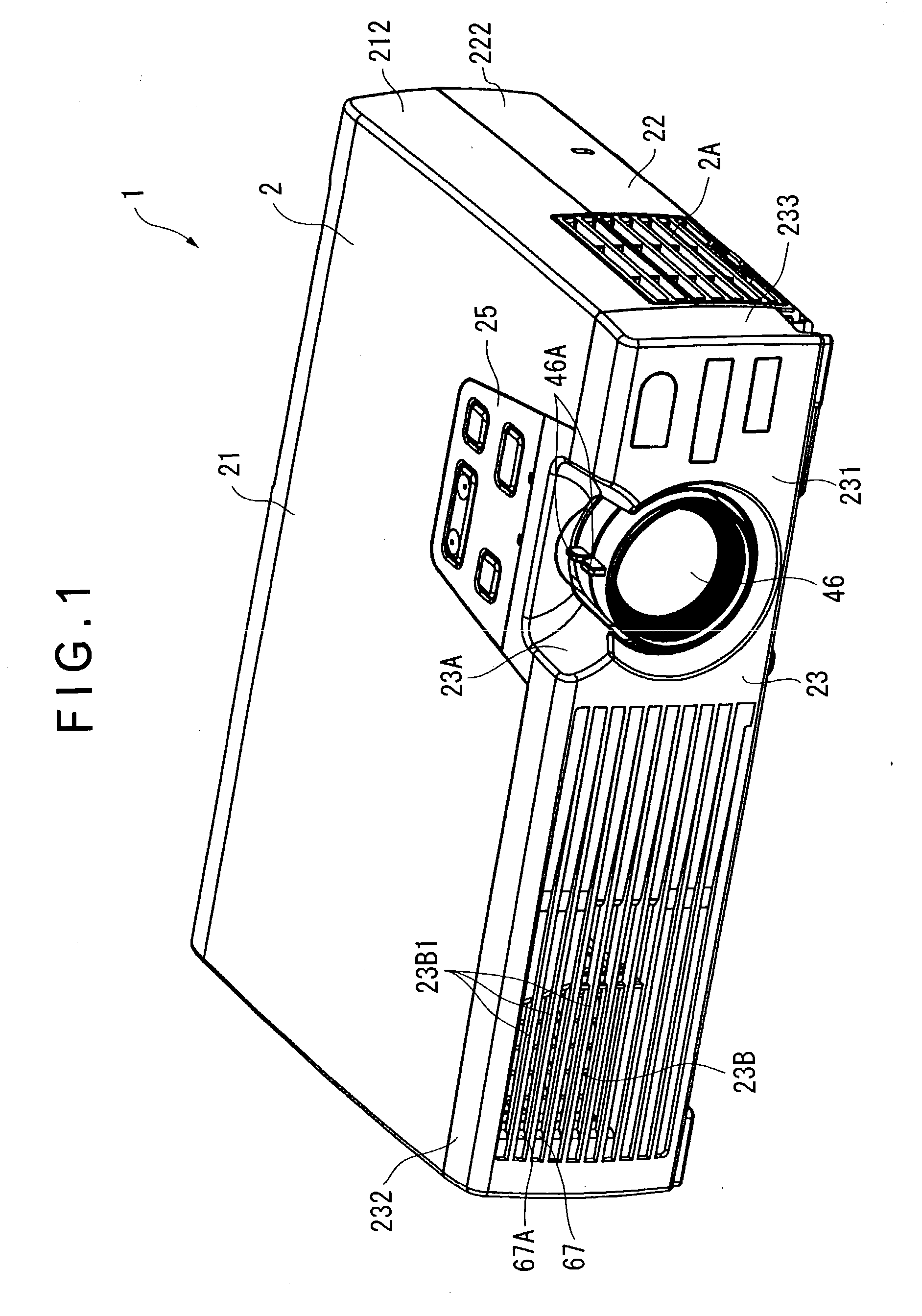
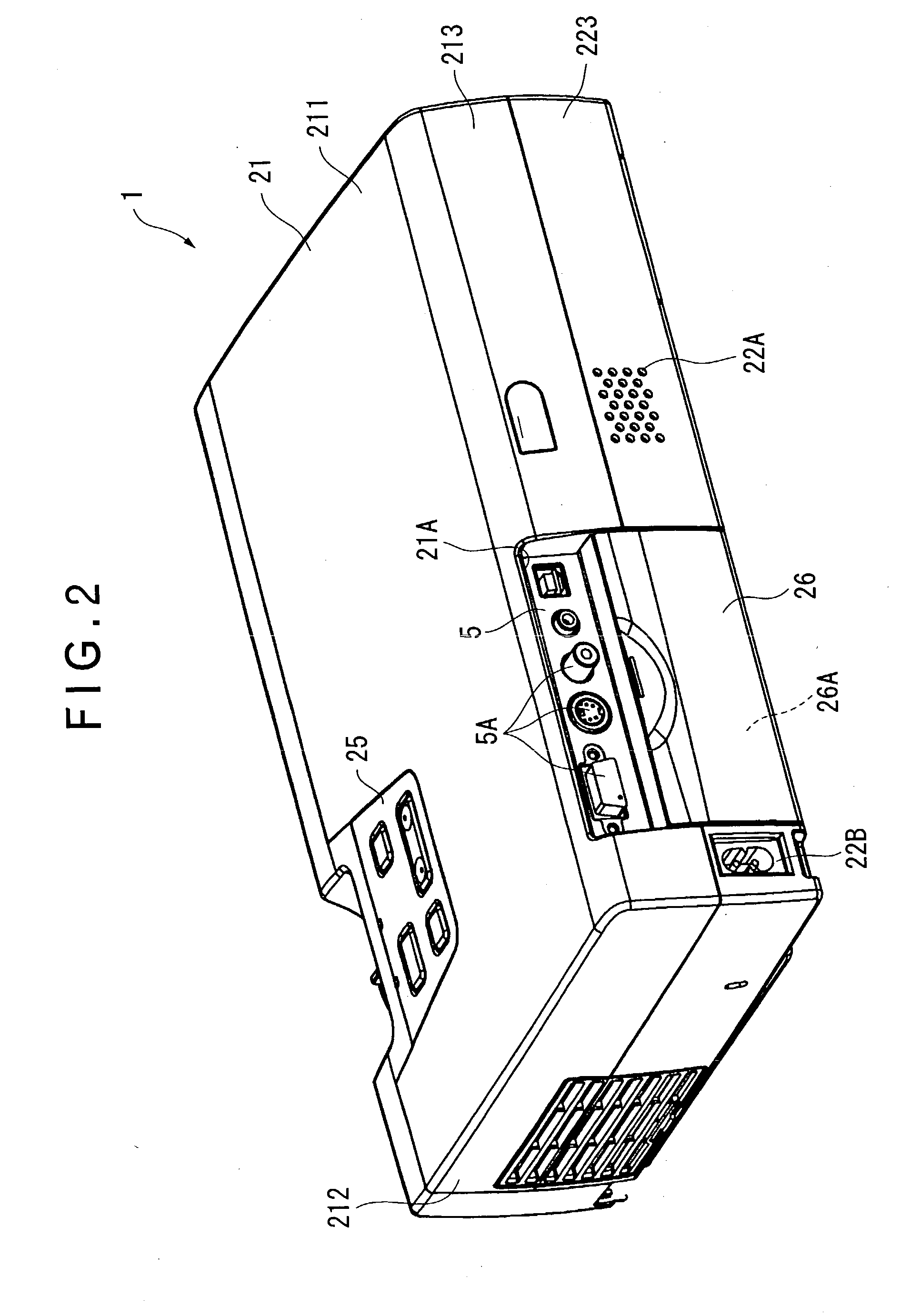
[0043] FIG. 1 is a perspective view of a projector 1 seen from above according to an embodiment of the present invention. FIG. 2 is a perspective view of the projector 1 seen from back side. FIG. 3 is a perspective view of the projector 1 seen from below.

[0044] As shown in FIGS. 1 to 3, the projector 1 has an exterior case 2 of approximately rectangular parallelepiped.

[0045] The exterior case 2 is a casing for accommodating a body of the projector 1, which includes an upper case 21, a lower case 22 and a front case 23 spanning over the front side of the cases 21 and 22. The cases 21 to 23 are respectively made of synthetic resin material.

[0046] As shown in FIG. 2, the upper case 21 includes an upper portion 211, a side portion 212 and a rear portion 213 respectively constituting the top side, lateral side and rear side of the proj...


PUM


Abstract

A projector according to the present invention is capable of simplifying a shield structure, sufficiently avoiding electromagnetic interference and reducing size thereof by highly densely installing the components thereof, the projector having a power source block (31) having a power source board (31B) installed with a transformer, a converter for converting an output of the transformer etc., the power source board (31B) being accommodated in a case member (31A) composed of metal for shielding electromagnetic wave from the installed circuit components, where a lower shield (33) is disposed to cover the case member (31A), the lower shield (33) having a support portion (31C) projecting upward from four corners on the upper side thereof and a light source driving block fixing portion (31F) extending downward from a front portion thereof, the support portion (31C) supporting a control board (5), the light source driving block fixing portion (32) fixing a light source driving block (32).

Description

[0001] 1. Field of the Invention[0002] The present invention relates to a projector having an electric optical device for modulating a light beam irradiated by a light source in accordance with image information.[0003] 2. Description of Related Art[0004] Conventionally, a projector has been used for presentation at a conference, scientific society and exhibition. Such projector forms an optical image by modulating a light beam irradiated by a light source with an optical modulator in accordance with image information to enlarge and project the optical image. The projector therefore has a driving circuit for driving the light source, a control board for controlling the optical modulator, and a power source for supplying electric power to the driving circuit and the control board.[0005] Enhancement in the luminance of the light source for improving performance and size reduction for improving portability are desired for such projector.[0006] However, since a light source driving block...

Claims


Application Information

Patent Timeline
Patent Type & Authority Applications(United States)
IPC IPC(8): G03B21/00
CPCG03B21/00G03B21/005
Inventor NAKANO, HIROHISA
Owner SEIKO EPSON CORP
Why Eureka
Try Eureka