
Operating device for an electrical appliance

an electrical appliance and operating device technology, applied in the direction of domestic stoves or ranges, pulse techniques, heating types, etc., can solve the problem of limited number of operating functions and other problems

Inactive Publication Date: 2003-09-25
E G O ELEKTRO GERAETEBAU GMBH
View PDF6 Cites 18 Cited by
  • Summary
  • Abstract
  • Description
  • Claims
  • Application Information

AI Technical Summary

Benefits of technology

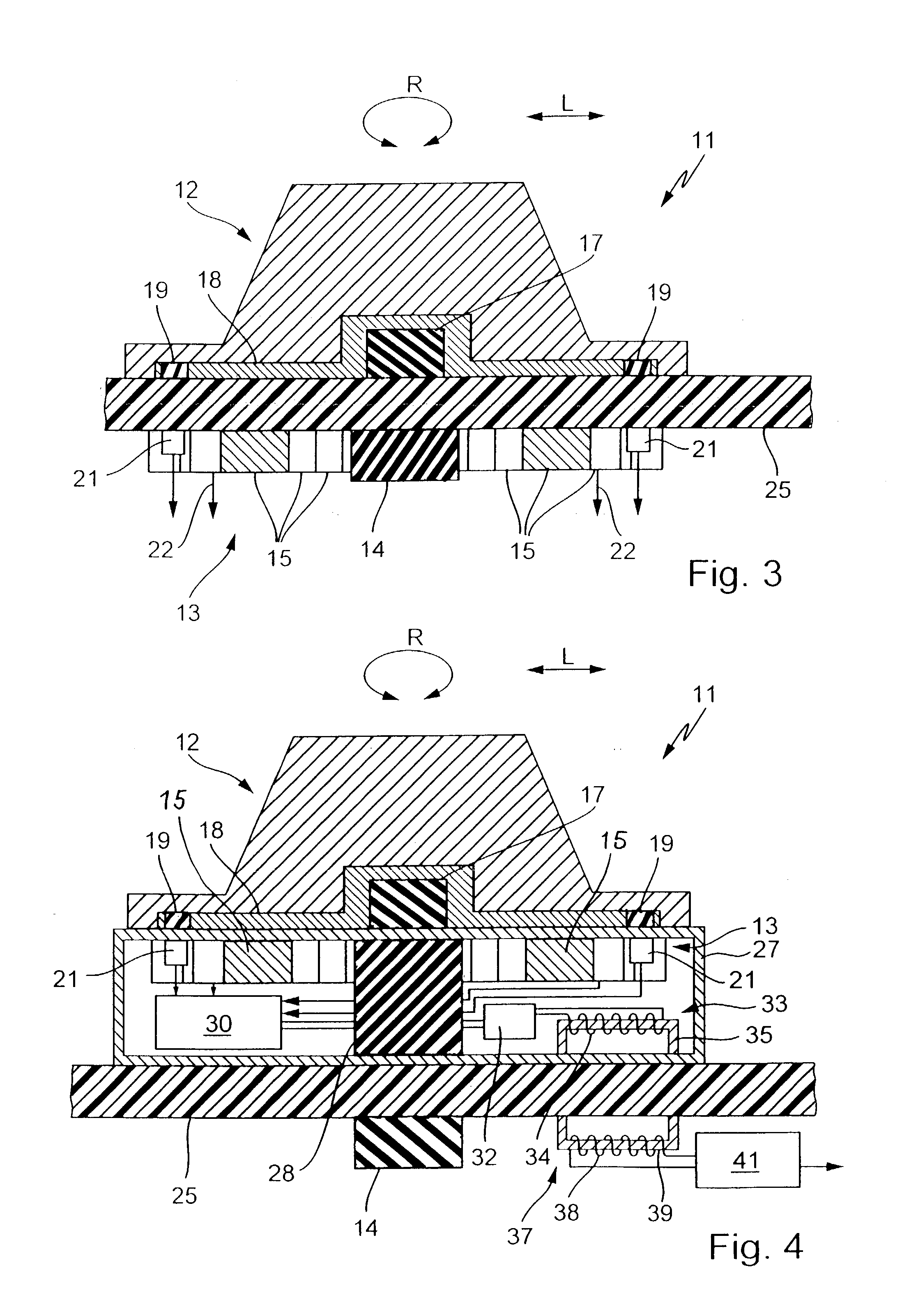
[0010] According to a further development of the invention, the bearing device can be constructed in such a way that the operating unit is removably fixed to a cover of the electrical appliance. For this purpose a holding power is provided, which is preferably non-contacting or has an external power effect. Advantageously use is e.g. made of holding magnets, which can be provided in the bearing device and / or on the electrical appliance cover. With such a construction it is possible to remove the operating unit, e.g. for safety reasons. This also makes it possible to operate several electrical appliances with the same operating unit.
[0012] In a particularly preferred development of the invention not only is the operating unit constructed so as to be removable from the cover, but this also applies to at least most of the bearing device. It is possible for the rotary toggle and bearing device to form a constructional unit or a separate operating unit. The latter can be fixed in different ways to a cover or the like of an electrical appliance and held there. It is merely necessary to either place the signalling means on the cover or, if they are also provided in the operating unit, to have a signal transmission from the operating unit to the electrical appliance. This can make it possible to bring about a simpler construction of the electrical appliance. The operating functionalities together with the detection of position signals are completely present in the operating device.
[0015] A guidance of the linear movement and in particular also the rotary movement can take place advantageously in contact-free manner by external power action, such as by magnetic power or force. Thus, such a guidance involves a certain expenditure. However, it has the advantage of being free from wear and of permitting a closed surface of the cover. Alternatively it is possible for certain variants of the invention to have guidance by mechanical guidance means.
[0020] To permit a clear detection of an operation of the rotary toggle as a linear operation, but so that it is appropriate for use, not too complicated or costly and can be readily detected, up to the release of a signal or up to a stop member, it should be shorter than the radius of the rotary toggle or the extension of the latter in the operating direction. This makes it possible to leave the dead centre of the rotary toggle, which is advantageously used as the point predetermining the linear operation, within the extension of the rotary toggle in the inoperative position.

Problems solved by technology

However, only a limited number of operating functions is possible.
Thus, such a guidance involves a certain expenditure.

Method used


Image

  • Operating device for an electrical appliance
  • Operating device for an electrical appliance
  • Operating device for an electrical appliance

Examples


Embodiment Construction

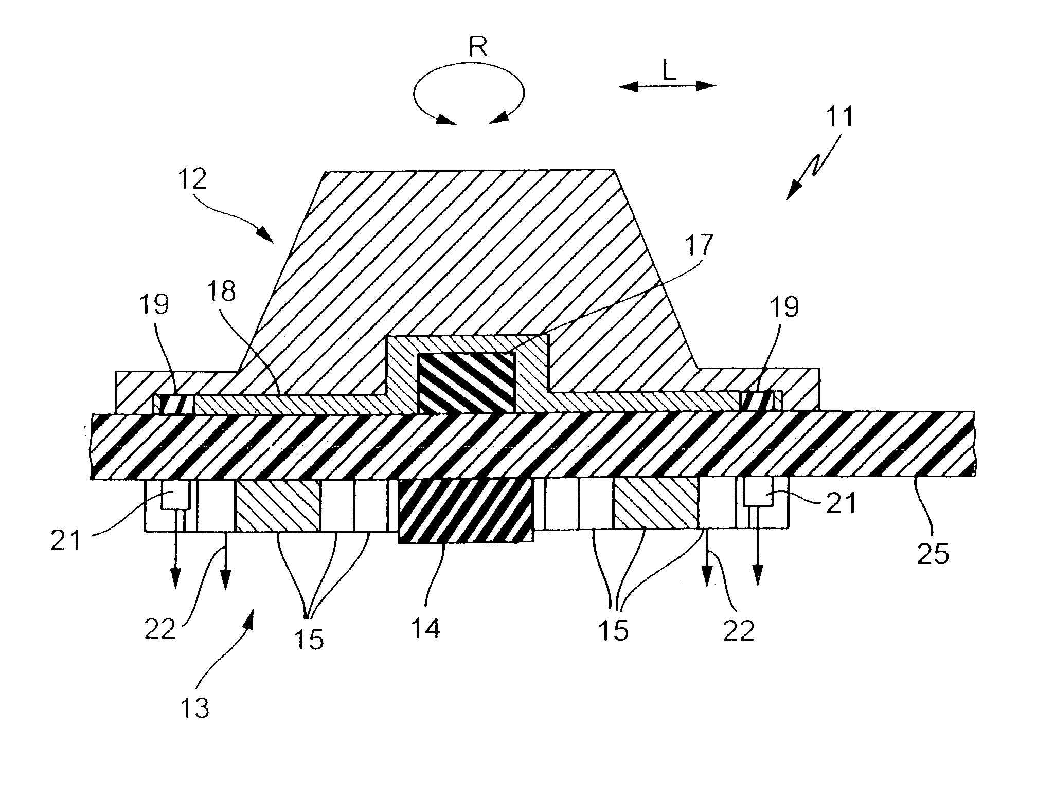
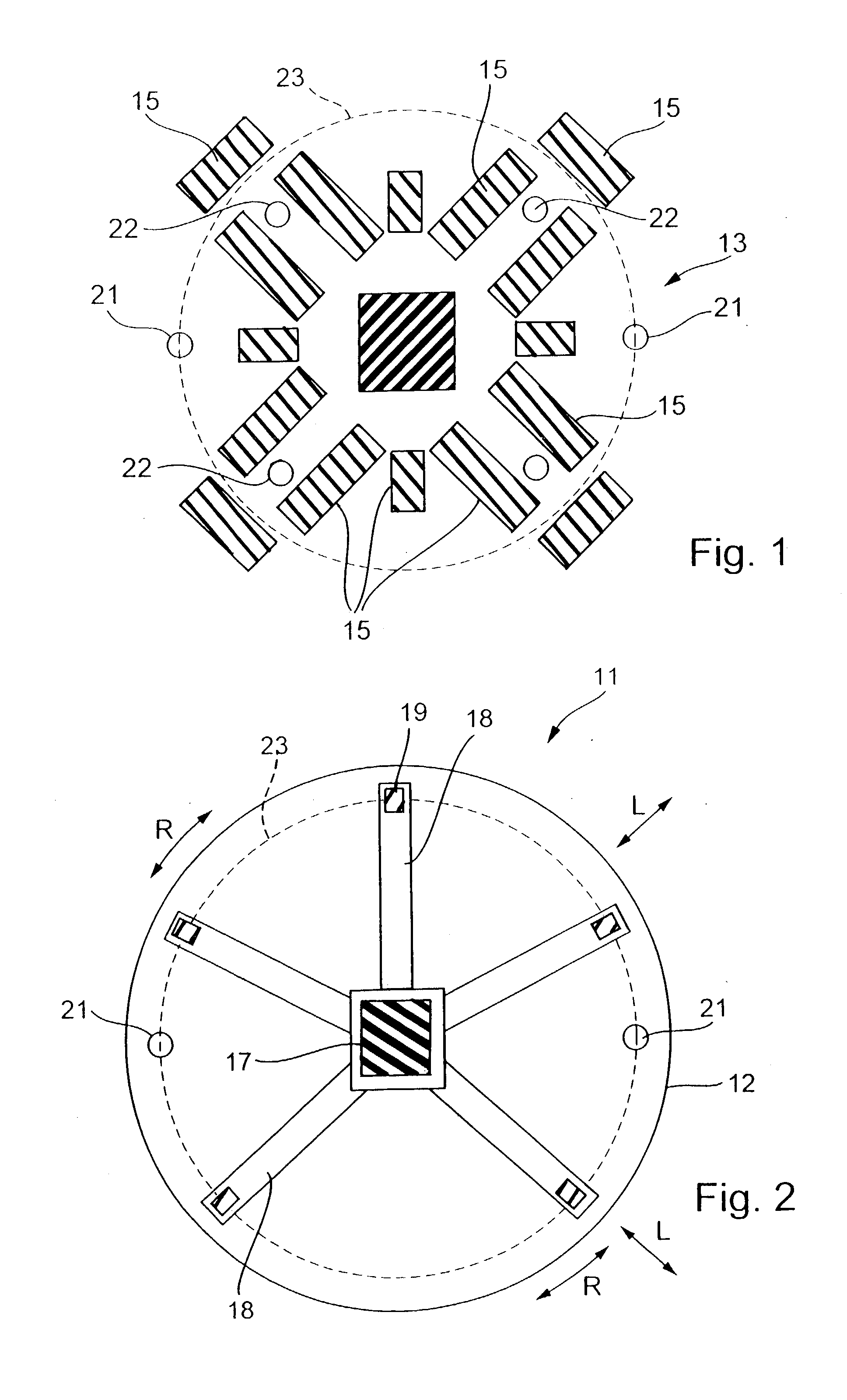
[0028] FIG. 1 shows a bearing device 13 for an operating unit 11, as can be seen in lateral section in FIGS. 3 and 4. The bearing device 13, as can be gathered from the two aforementioned drawings, can either be placed under a glass ceramic hob 25 or below the top surface 26 of a holding module 27.

[0029] The bearing device 13 has a first central magnet 14 used for centring the rotary toggle 12. There are also several guide magnets 15 arranged around the first central magnet 14 and which form, as can be seen clearly in FIG. 1, a linear guide for the rotary toggle 12. The arrangement roughly corresponds to a guide link, such as could also be constructed according to the invention for mechanical guides. In connection with the construction of the bearing device 13 or the arrangement of the guide magnets 15, it is mainly a question of forming a closed border with several longitudinally extending areas. At the end of the longitudinal areas is once again provided a guide magnet 15 for limi...


PUM


Abstract

In an embodiment of the invention an operating device for a glass ceramic hob (25) can be provided and has an operating unit (11). The operating unit (11) has a rotary toggle (12), which is magnetically mounted on a glass ceramic hob (25). A bearing device (13) below the glass ceramic hob has guide magnets (15), which form a magnetically acting guide link, which permits both a rotary movement (R) and a linear movement (L) of the rotary toggle (12). The rotary toggle (12) has signalling magnets (19) along its outer circumference and with them are associated beneath the hob (25) Hall sensors (21). Further Hall sensors (22) are positioned between the guide magnets (15). A random movement (R, L) of the rotary toggle (12) can be detected with the Hall sensors (21, 22). The operating unit (11) can be removed. The glass ceramic hob (25) requires no openings or the like.

Description

FIELD OF APPLICATION AND PRIOR ART[0001] The invention relates to an operating device for an electrical appliance, preferably an electrical heating appliance such as a cooker.[0002] DE 198 59 105 discloses an operating device for an electrical appliance having a type of magnetic sliding key. The sliding key is placed on a glass ceramic plate of a cooker and has a magnetic guide. By so-called keying, i.e. linear movements in different and in particular opposing directions, it is possible to release switching signals and therefore operate the electrical appliance. However, only a limited number of operating functions is possible.[0003] Problem and Solution[0004] The problem of the invention is to provide an operating device for an electrical appliance permitting further extensions to operating functionalities.[0005] This problem is solved by an operating device having the features of claim 1. Advantageous and preferred developments of the invention form the subject matter of further c...

Claims


Application Information

Patent Timeline
Patent Type & Authority Applications(United States)
IPC IPC(8): F24C7/02F24C7/08F24C15/00H01H19/20H01H25/00H01H25/06H01H36/00H05B3/74
CPCF24C7/083H05B3/746H01H36/0066H01H25/008H03K17/97H03K2217/94068
Inventor SCHILLING, WILFRIED
Owner E G O ELEKTRO GERAETEBAU GMBH
Learn More