
Low-order aberration correction using articulated optical element

a technology of articulated optical elements and aberration correction, applied in the field of optics, can solve the problems of reducing the average intensity of a focused laser beam, difficult deformation of mirrors, and high manufacturing cos

Inactive Publication Date: 2003-11-06
RAYTHEON CO
View PDF5 Cites 27 Cited by
  • Summary
  • Abstract
  • Description
  • Claims
  • Application Information

AI Technical Summary

Problems solved by technology

The result is an optical distortion (or aberration) that reduces the average intensity of a focused laser beam due to beam spreading and causes spatial and temporal fluctuations in the beam due to scintillation.
However, deformable mirrors are difficult and expensive to manufacture and require a high throughput processor, called a real-time reconstructor.

Method used


Image

  • Low-order aberration correction using articulated optical element
  • Low-order aberration correction using articulated optical element
  • Low-order aberration correction using articulated optical element

Examples


Embodiment Construction

[0017] Illustrative embodiments and exemplary applications will now be described with reference to the accompanying drawings to disclose the advantageous teachings of the present invention.

[0018] While the present invention is described herein with reference to illustrative embodiments for particular applications, it should be understood that the invention is not limited thereto. Those having ordinary skill in the art and access to the teachings provided herein will recognize additional modifications, applications, and embodiments within the scope thereof and additional fields in which the present invention would be of significant utility.

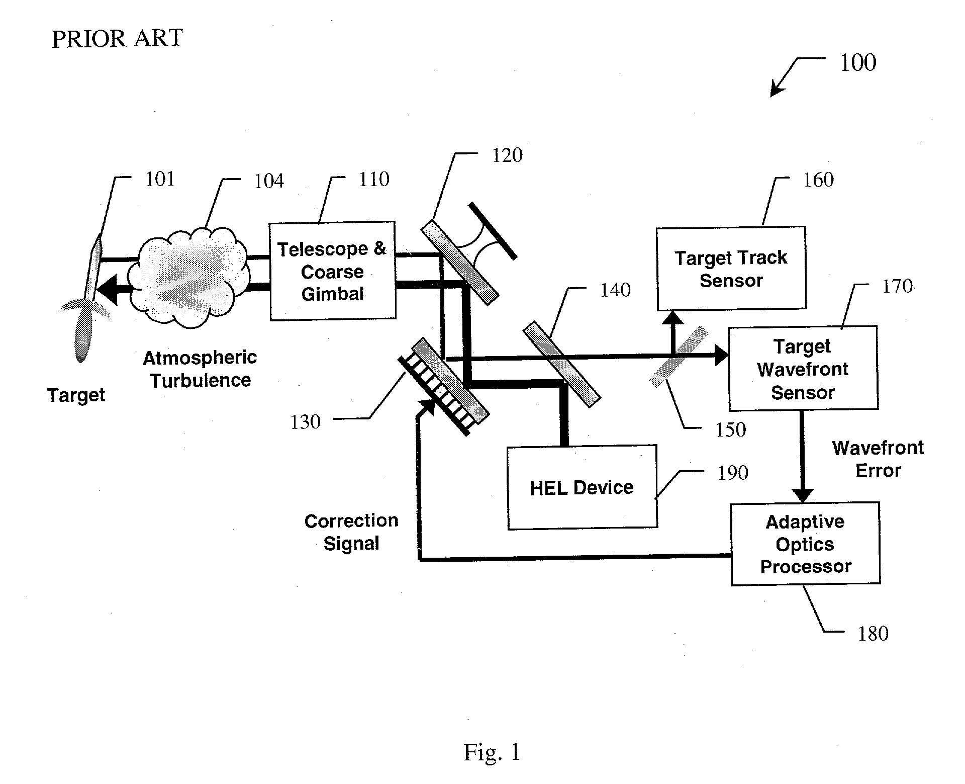
[0019] A simplified optical schematic of a conventional laser beam control architecture 100 is shown in FIG. 1. A beam director, generally consisting of a Telescope and 2-axis Coarse Gimbal 110, is commanded to the line-of-sight of a Target 101 based on an external cue (acquisition or coarse tracking system not shown). A Target Track Sensor 160 acq...


PUM


Abstract

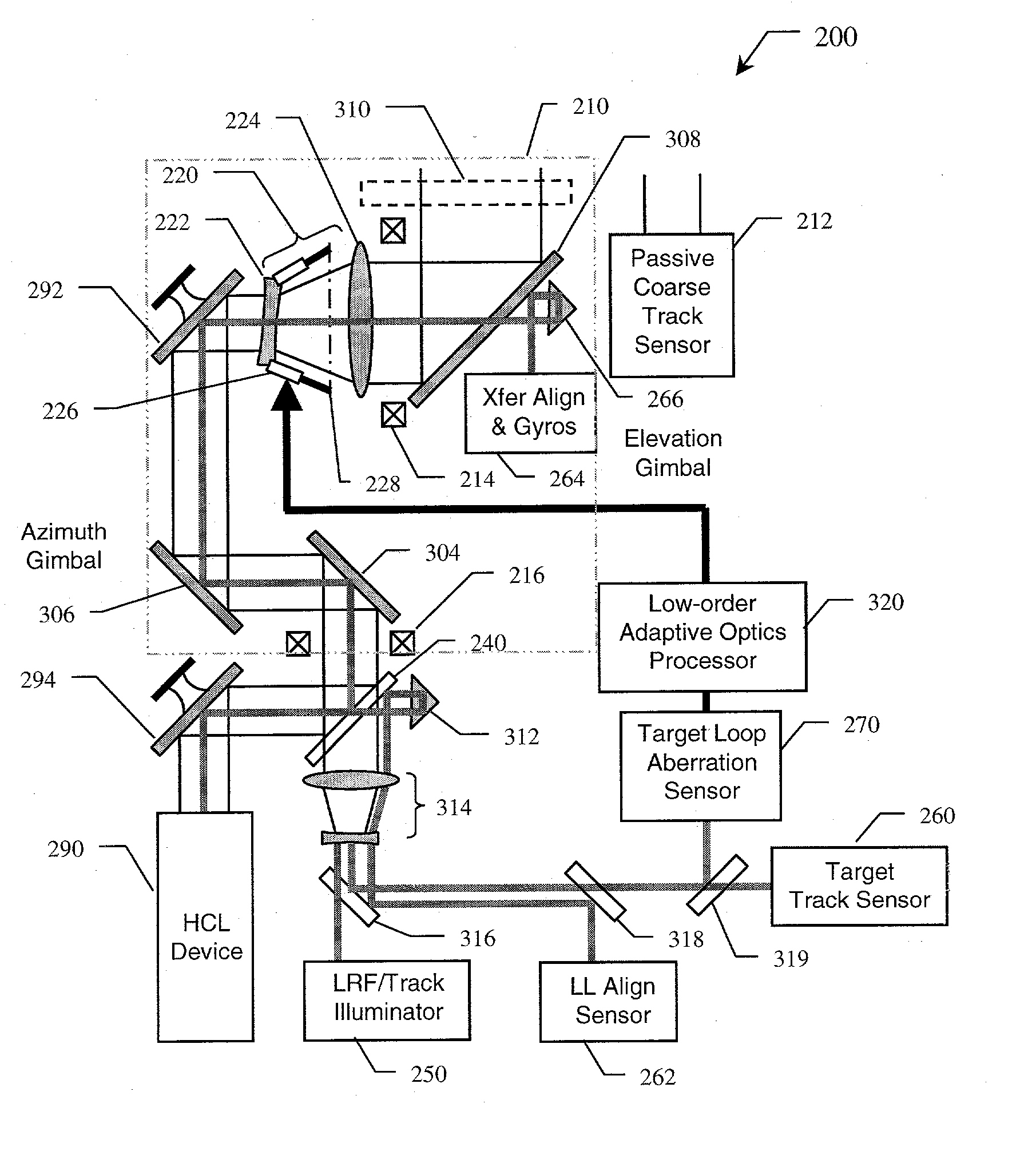
A system (200) for effecting low-order aberration correction of a beam of electromagnetic energy. The inventive system (200) includes a first mechanism (220), including at least one articulated optical element (222), for receiving and correcting the beam; a second mechanism (270) for generating a signal indicative of the aberrations to be corrected; and a third mechanism (226), responsive to the second mechanism (270), for adjusting the position of the optical element (222) to generate an output beam that is at least partially compensated with respect to the aberrations. In the preferred embodiment, the first mechanism (220) is a telescope comprising a fixed primary lens or mirror (224) and an articulated secondary lens or mirror (222). The second mechanism (270) includes a wavefront error sensor for detecting aberrations in the received beam. The third mechanism includes a processor (320) responsive to the second mechanism (270) for providing a correction signal, and six linear actuator struts (226) arranged in a non-redundant hexapod configuration to move the secondary lens or mirror (222) in at least five degrees-of-freedom in response to the correction signal.

Description

[0001] 1. Field of the Invention[0002] The present invention relates to optics. More specifically, the present invention relates to systems and methods for correcting high-power beams of electromagnetic energy.[0003] 2. Description of the Related Art[0004] High power lasers are being considered for a variety of industrial, commercial, and military applications, including materials processing, satellite imaging, target tracking and identification, and directed energy weapons (DEW). Laser DEW systems generally involve the use of a high energy laser (HEL) to irradiate and destroy a target. To achieve performance objectives, many of these applications require that the laser beam be accurately steered and optimally focused. Steering involves line-of-sight control while focusing involves wavefront error correction.[0005] Atmospheric turbulence produces density variations in the air that cause optical pathlength differences across a given beam path. The result is an optical distortion (or ...

Claims


Application Information

Patent Timeline
Patent Type & Authority Applications(United States)
IPC IPC(8): G02B26/06
CPCG02B26/06F41H13/005
Inventor BYREN, ROBERT W.COOK, LACY G.GRIFFIN, WILLIAM S.
Owner RAYTHEON CO
Learn More