Wrist with decoupled motion transmission

a technology of decoupling motion and transmission cable, which is applied in the field of wrist, can solve the problems of less likely to develop a permanent stretch, adversely affecting the sensitivity or "feel" a user often requires, and achieves the effects of reducing inertia of moving elements, reducing the stretch on the transmission cable, and increasing the performance of the devi

Inactive Publication Date: 2003-11-06
MOREYRA MANUEL RICARDO
View PDF1 Cites 188 Cited by
  • Summary
  • Abstract
  • Description
  • Claims
  • Application Information

AI Technical Summary

Benefits of technology

0005] The present invention provides a wrist in which the transmission of motion, force and / or torque around a revolute joint can be accomplished without coupling. The motion of its adjacent link does not affect the relative motion of the decoupled element. This construction allows mounting the actuators on other elements of a mechanism, so that only linkage elements move the end-effector. Thus reducing inertia of the moving elements and increasing performance of the device. The decoupled motion of the end-effector or links is achieved by routing their transmission cables around idler pulleys placed parallel to the joint rotation axis on an optimal position such that any stretch on the transmission cable is minimized. This construction may be use for robotic surgical tools that have two independently driven jaws, decoupled and orthogonal from its articulating wrist. This surgical device may also be used in grasping, cutting, suturing or alike operations.

Problems solved by technology

Thus, the cable is less likely to develop a permanent stretch over multiple uses, which can cause backlash and adversely affect the sensitivity or "feel" a user often requires while operating the end-effector.

Method used


Image

  • Wrist with decoupled motion transmission
  • Wrist with decoupled motion transmission
  • Wrist with decoupled motion transmission

Examples


Embodiment Construction

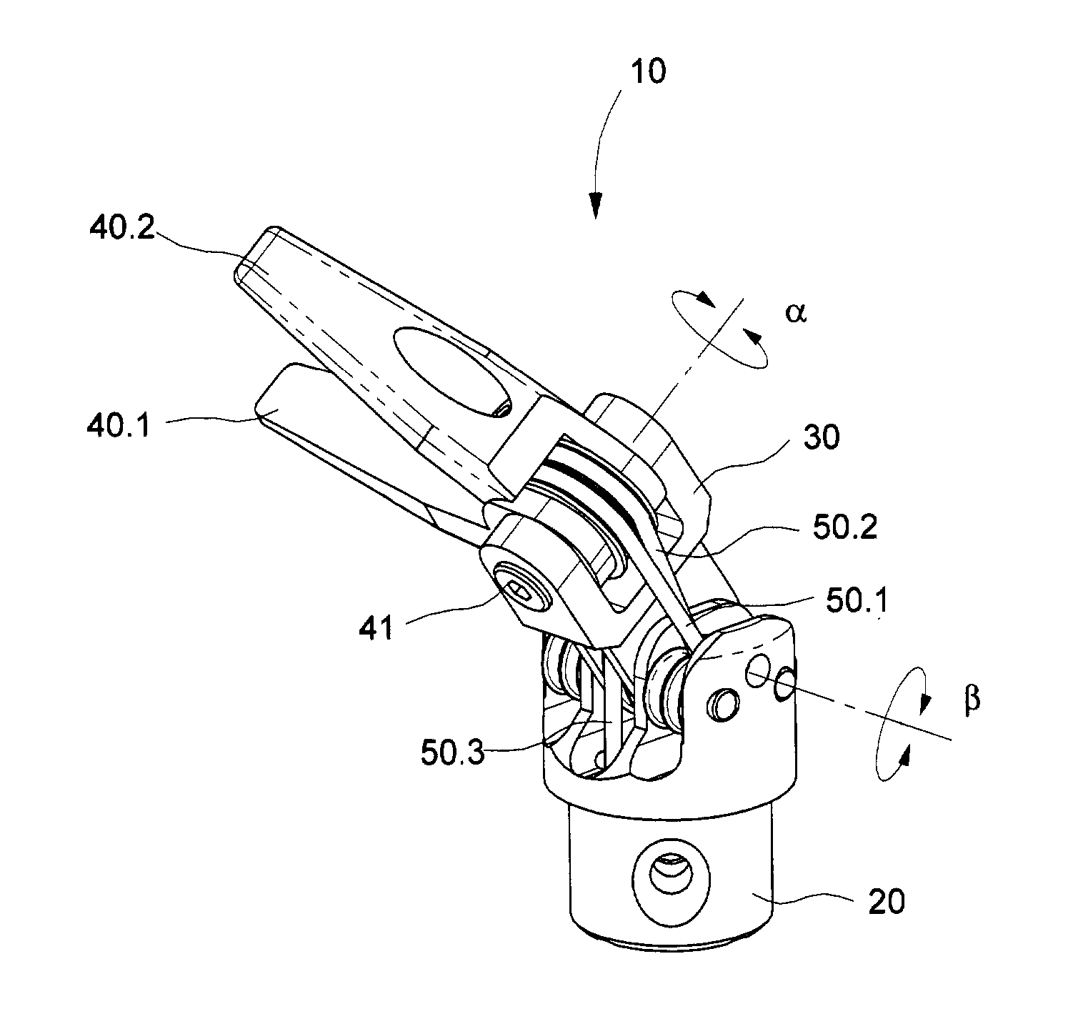
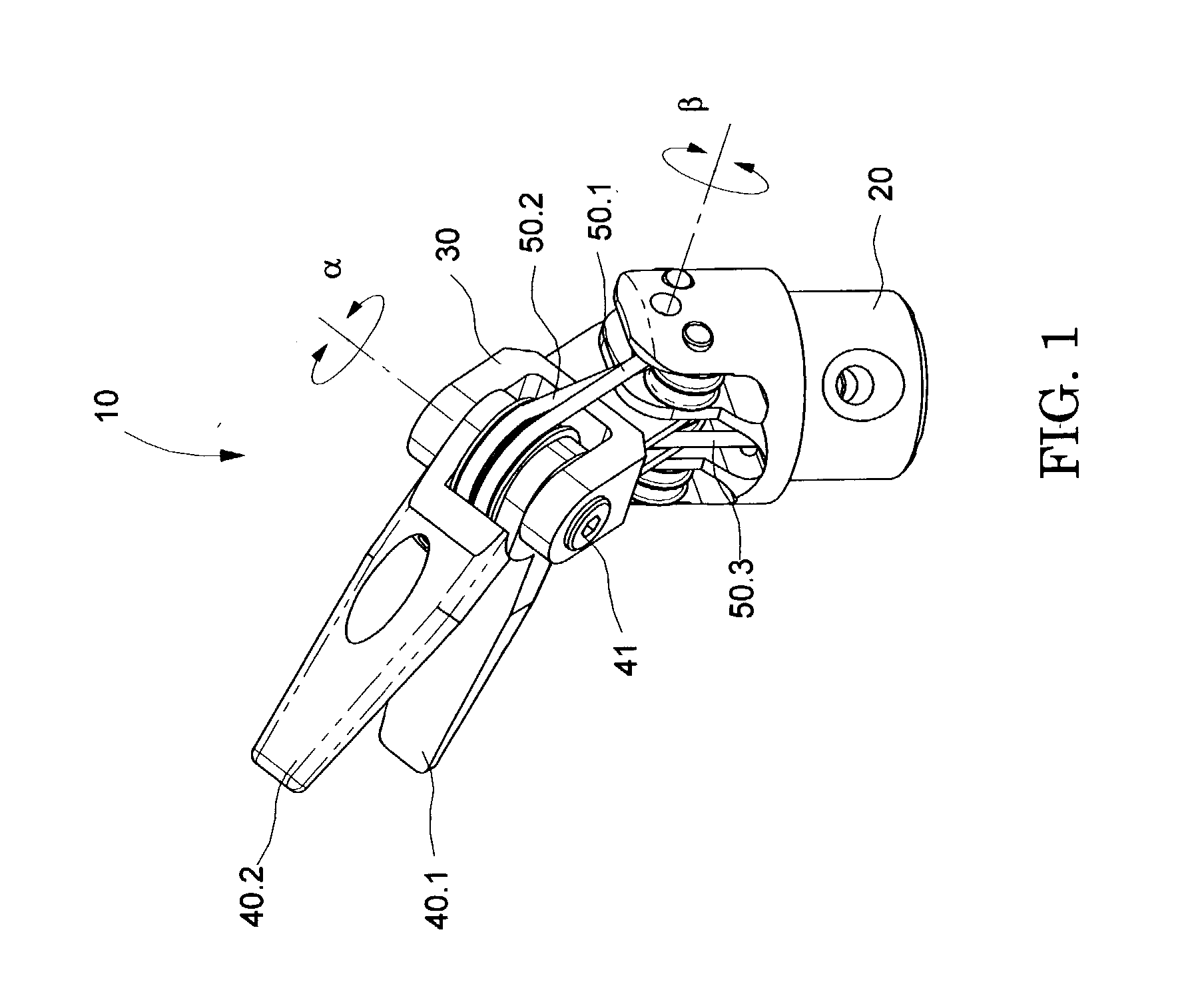
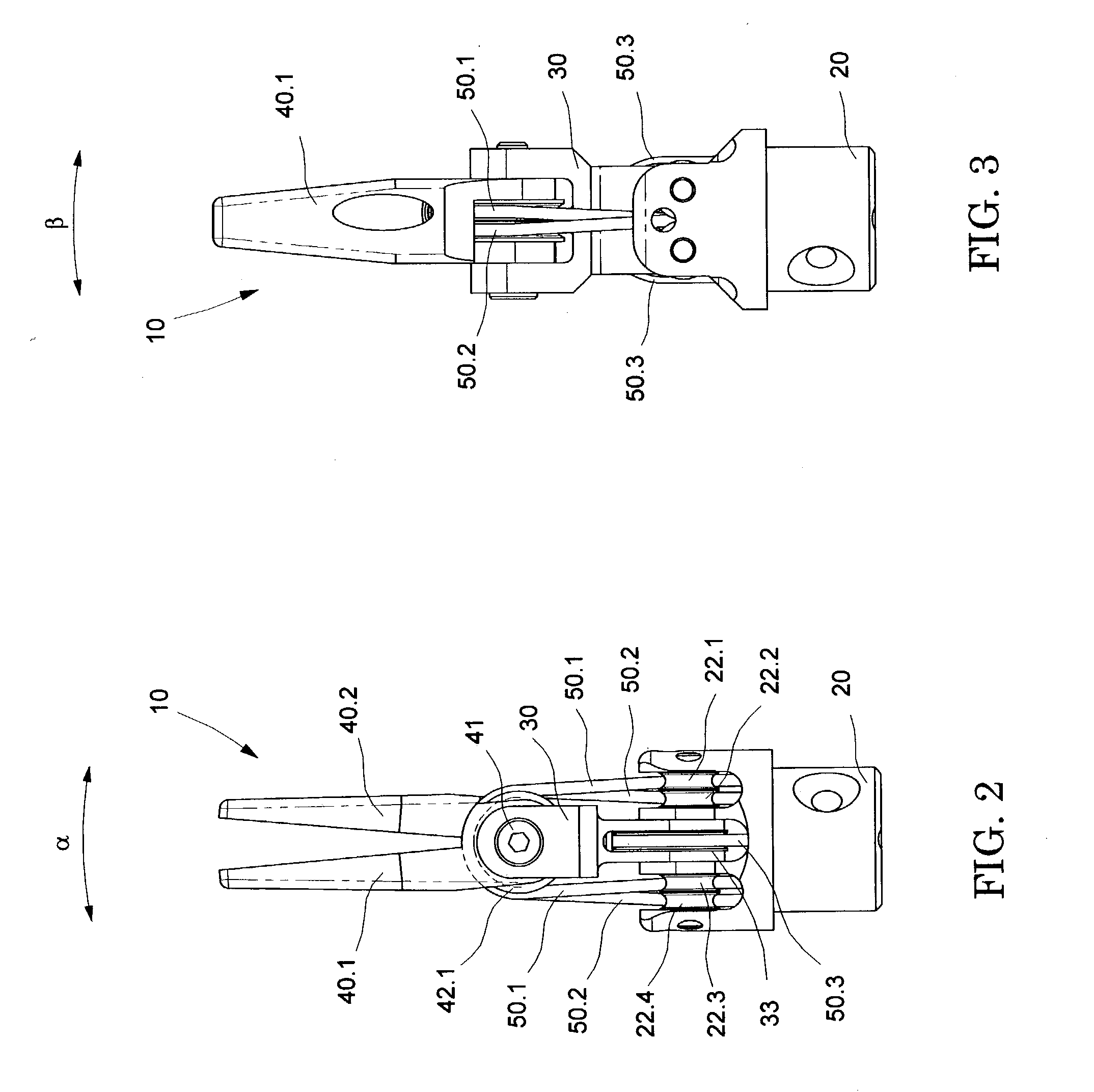
[0032] FIGS. 1 through 4 illustrate a wrist and tool 10. The end-effector consists of two jaws 40.1 and 40.2, each jaw is rigidly coupled to their respective drive pulleys 42.1 and 42.2. Both jaws rotate around .alpha. on a common shoulder screw 41 that is mounted to the jaws base 30. An orthogonal wrist rotation .beta. occurs when the jaws base rotates with its pulley 33 around pin 31.

[0033] FIG. 4 shows an exploded view of the wrist mechanism 10. The jaw 40.1 has a ring 40.1 a machined around its rotation axis. Each drive pulley 42.1 and 42.2 mounts on its jaw ring with its respective cable attached. Each jaw 40.1 and 40.2, pulley 42.1 and 42.2, and the cable 50.1 and 50.2 (not shown in FIG. 4) is rigidly coupled together with its setscrew 43.

[0034] Each jaw 40.1 and 40.2 can rotate independently around the shoulder screw 41, .alpha. axis. When the two jaws rotate on the same direction, one wrist articulation motion is accomplished. And when the jaws rotate on opposite direction, ...


PUM


Abstract

The present invention is a wrist mechanism and a method for making robotic devices in which the transmission of motion, force and/or torque around a revolute joint can be accomplished without coupling. This construction allows mounting the actuators on the base or lower elements of a mechanism, so that only linkage elements move the end-effector. Thus reducing inertia of the moving elements and increasing performance of the device. The decoupled motion of the end-effector or links is achieved by routing their transmission cables around idler pulleys placed parallel to the joint rotation axis on an optimal position such any stretch on the transmission cable is minimized. In particular, this construction can be use for robotic surgical tools that have two independently driven jaws, decoupled and orthogonal from its articulating wrist.

Description

[0001] This application claims priority from commonly owned U.S. Provisional Patent Application No. 60 / 376,964 titled Articulated Wrist And Tool With Decoupled Motion Transmission, presently pending, which is hereby incorporated by reference in its entirety.[0002] Minimally invasive surgical robotic systems are being developed to increase surgeon's dexterity when working within an internal surgical location. Such minimally invasive procedures are conducted by inserting surgical instruments through small incisions on the skin of the patient. The use of dexterous surgical instruments to manipulate tissues and suture would facilitate the performance of an endoscopic surgical procedure. A manually or robotically actuated surgical device that can articulate as well as actuate reliably would minimize patient risk and operating time.[0003] Current minimally invasive surgical tools have many drawbacks. Most endoscopic tools have rigid shafts and are constrained to approach the workspace fro...

Claims


Application Information

Patent Timeline
Patent Type & Authority Applications(United States)
IPC IPC(8): A61B19/00
CPCA61B19/2203A61B2019/2234Y10T74/20305A61B2019/2246A61B2019/2242A61B34/30A61B34/71A61B2034/305A61B2034/715
Inventor MOREYRA, MANUEL RICARDO
Owner MOREYRA MANUEL RICARDO
Why Eureka
Try Eureka