
Electrochemical cell and a method for the manufacture thereof

a technology of electrochemical cells and electrodes, applied in the field of electrochemical cells, can solve the problems of non-conductive reaction products, loss of conductivity, and reduction of the three-phase limit or the electrode face, and achieve the effects of improving the electrode efficiency, reducing the reactivity, and reducing the electrochemical efficiency of these portions

Inactive Publication Date: 2003-12-18
DANMARKS TEKNISKE UNIV
View PDF5 Cites 4 Cited by
  • Summary
  • Abstract
  • Description
  • Claims
  • Application Information

AI Technical Summary

Benefits of technology

[0020] The object of the invention is therefore to provide an electrochemical cell, where a strong mechanical anchoring of the electrode to the surface of the electrolyte has been established without significantly reducing the efficiency of the electrode.
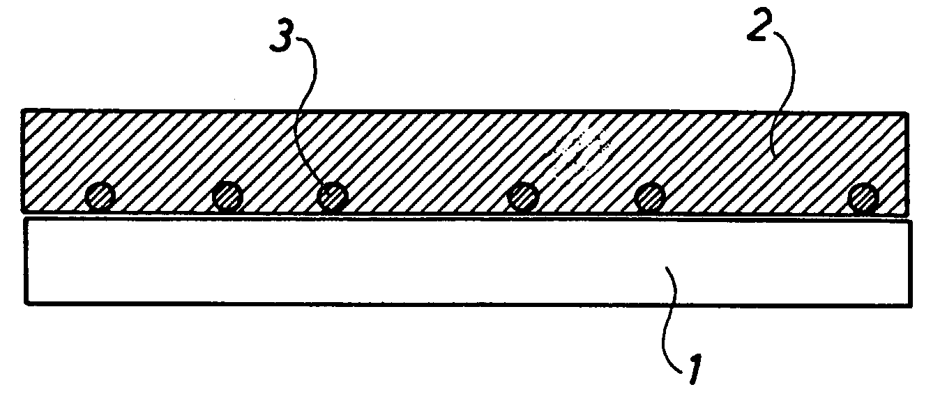
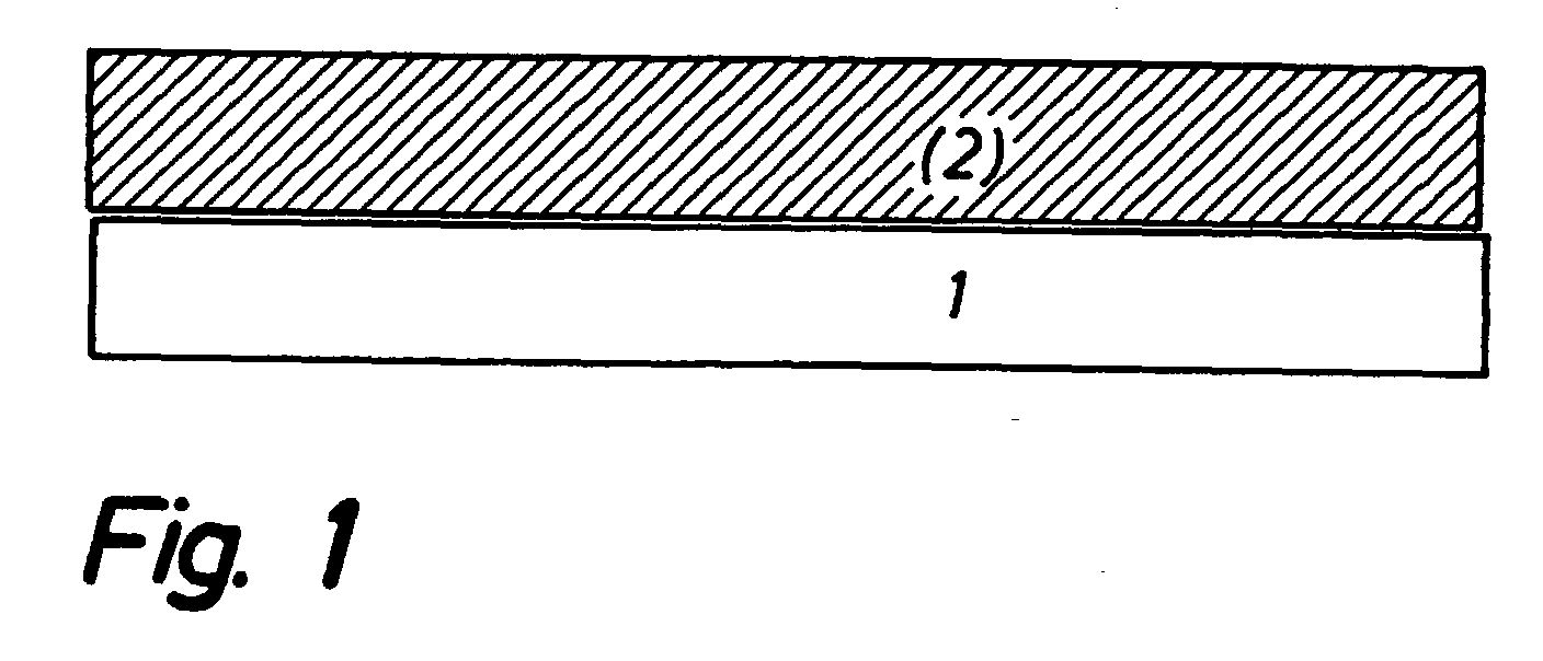
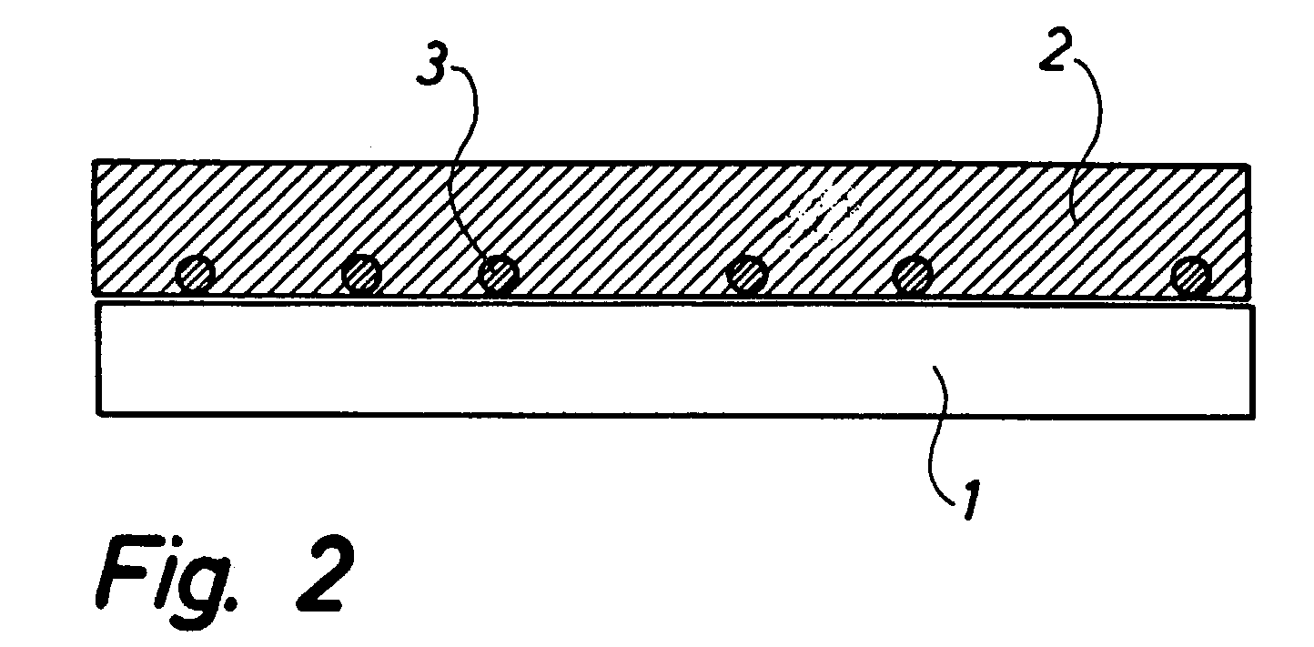
[0021] An electrochemical cell of the above type is according to the invention characterised in that a noncovering layer of particles of another composition than the electrolyte is applied and sintered onto a sintered electrolyte. These particles can for instance be applied by way of spraying a suspension thereon. The particles comprise a material being reactive towards the electrolyte to a suitable degree. A sintering of anchoring particles onto the electrolyte results in a very strong anchoring of said particles to the surface of the electrolyte. Subsequently, the electrode can be applied by way of for instance a wet-ceramic process and be attached to the electrolyte by means of the anchoring particles at a process temperature significantly lower than the sintering temperature of the electrolyte and furthermore significantly lower than the temperature necessary in mechanical respect for obtaining a direct sintering of the electrode material onto the electrolyte. The latter low process temperature renders it possible to obtain a limited reactivity between the electrolyte and the electrode material at the portions of said electrolyte not being covered by anchoring particles, and accordingly the electrochemical efficiency of these portions is high. A suitably limited covering of anchoring particles on the electrolyte has the effect that the loss of the active electrolyte surface is compensated for by the improved efficiency of the electrode, said improved efficiency being obtained by a lowering of the process temperature.

Problems solved by technology

A first cause of loss is formation of nonconductive reaction products at the interface.
Another cause of loss is reduction of the three-phase limit or the electrode face by way of a reduction of the porosity of the electrode.
A third cause is found in loss of conductivity due to a mixing of the two materials, viz. reactivity or reciprocal solubility.
However, in addition it appears that these high temperatures may cause formation of reaction products at the interface, said reaction products reducing the efficiency of the electrode.
However, it is difficult to corrugate a very thin electrolyte, viz. an electrolyte of a thickness of 5 to 25 .mu.m, without causing errors, such as through errors and porosities.
Consequently, it is difficult to sinter electrolyte particles onto a tight electrolyte because typically the electrolyte is not sinteringly active.
In addition, it is difficult to obtain a tight electrolyte by way of sintering while electrolyte particles are simultaneously sintered thereon, said electrolyte particles projecting from the surface.
Typically, such particles cause through errors and porosities.
However, such a procedure involves a high risk of damaging the electrolyte layer, which is typically of a thickness of 2 to 15 .mu.m corresponding to the dimension of efficient anchoring particles.

Method used


Image

  • Electrochemical cell and a method for the manufacture thereof
  • Electrochemical cell and a method for the manufacture thereof
  • Electrochemical cell and a method for the manufacture thereof

Examples


example 2

[0039] The symmetrical cells of FIG. 3 are manufactured as follows. A noncovering layer of TiO.sub.2 anchoring particles is sprayed onto sintered 8YSZ electrolyte foils, said layer of TiO.sub.2 anchoring particles being produced by ball milling of TiO.sub.2-agglomerates and isolation of a particle fraction of approximately 5 to 20 .mu.m through sedimentation.

[0040] The foils with anchoring particles sprayed thereon are sintered at 1150.degree. C. / 2 h, and subsequently a 20 .mu.m porous composite LSM / 8YSZ electrode is applied in two layers, and two sinterings at 1100.degree. C. / 2 h are carried out. Subsequently, the two symmetrical cells are frozen in water on a freezing surface and cut into test pieces of 4 times 4 mm.sup.2. The test pieces are provided with an LSM current collector and mounted between Pt grid. The electrodes are characterised by impedance spectroscopy at 700 to 1000.degree. C. in air while subjected to an AC amplitude of 14 mV RMS about an open voltage (ocv).

[0041]...


PUM

PropertyMeasurementUnit
temperaturesaaaaaaaaaa
thicknessaaaaaaaaaa
thicknessaaaaaaaaaa

Abstract

Electrochemical cell, such as an SOFC, comprising a porous solid electrode (2) in contact with an electrolyte (1), which has been treated so as to become gasproof before the electrode is applied. According to the invention, this contact has been mechanically improved by sintering anchoring particles (3) of for instance TiO2 onto the electrolyte (1). Subsequently, the electrode (2) can be sintered thereon at a temperature lower than hitherto known while still obtaining a sufficient, mechanical attachment in the contact. The latter lowering of the process temperature results in an improved efficiency of the electrode (2), and it allows the use of electrodes which are usually reactive towards the electrolyte at comparatively higher process temperatures.

Description

[0001] The invention relates to an electrochemical cell comprising an electrolyte and a porous electrode.[0002] A common feature of such electrochemical cells is the interface between the ceramic surface of the electrolyte and the ceramic / metallic / composite electrode must meet two vital criteria, viz. a) mechanical integrity; and b) electronic and / or ionic contact.[0003] The requirement to mechanical integrity is essentially based on the fact that the electrode must not let go of the electrolyte. Typically, electrodes can be applied onto electrolytes by way of wet-ceramic processes followed by a sintering, or by way of rather advanced methods, such as CVD, laser ablation etc at an increased temperature. The two materials are joined at a temperature referred to as the process temperature below. It is often advantageous to use a relatively high process temperature because such a temperature results in a good mechanical adhesion through a reaction between the two materials.[0004] When ...

Claims


Application Information

Patent Timeline
Patent Type & Authority Applications(United States)
IPC IPC(8): H01M4/86H01M4/88H01M4/90H01M8/1226H01M8/124
CPCH01M4/8621H01M4/8885H01M4/9016H01M4/9025Y10T29/49108H01M8/1226H01M8/124Y02E60/521Y02E60/525H01M4/9033Y02P70/50Y02E60/50
Inventor LINDEROTH, SORENPRIMDAHL, SOREN
Owner DANMARKS TEKNISKE UNIV
Learn More