Dispenser for the discharge of flowable media

a flowable media and discharging technology, applied in the field of discharging devices, to achieve the effect of simple and compact construction

Inactive Publication Date: 2004-01-01
APTAR RADOLFZELL
View PDF6 Cites 20 Cited by
  • Summary
  • Abstract
  • Description
  • Claims
  • Application Information

AI Technical Summary

Benefits of technology

0004] Object of the invention is to provide a dispenser, whose discharge process is largely independent of the nature of the operation by t

Problems solved by technology

When operating such dispensers it is always a problem to make the discharge process independent of the individual operation by

Method used


Image

  • Dispenser for the discharge of flowable media
  • Dispenser for the discharge of flowable media
  • Dispenser for the discharge of flowable media

Examples


Embodiment Construction

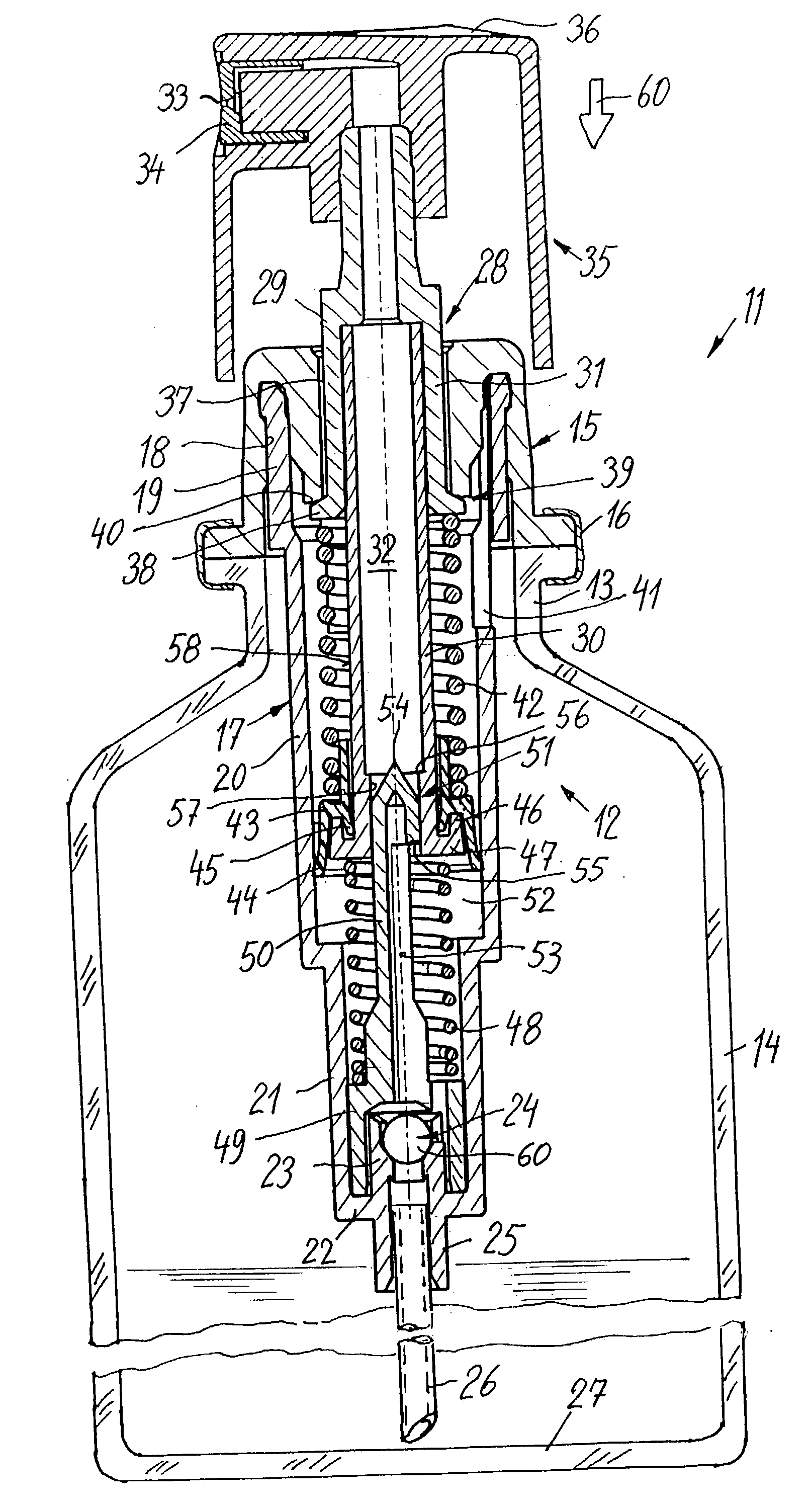
[0022] FIG. 1 shows a dispenser 11 with a pump 12, which is mounted on the neck 13 of a container 14 constructed like a glass bottle and projects into the same with the greatest part of its longitudinal extension. The pump has a base casing, which is fixed on the bottle neck 13 by means of a crimp seal 16.

[0023] Into the base casing 15 is snapped an elongated cylinder body 17, namely in an axial annular groove 18 between an outer part and an inner part of the base casing. Below its snapping-in portion, the cylinder body forms a pump cylinder 20 and following on to the same a diameter-reduced, also cylindrical cylinder portion 21. The latter terminates in a base 22 on which is inwardly constructed part of a cage 23 for a ball intake valve 24 and connected thereto a connection 25 extends outwards and into it is inserted a suction tube 26, which extends to the container bottom 27.

[0024] Into the cylinder 20 projects a piston 28, which has a tubular piston rod 29, which is assembled fro...


PUM


Abstract

A dispenser for flowable media is provided, which operates in user-independent manner with respect to the pressure buildup and dosage quantity. On pressing on an operating head (35) a piston rod (29) is forced into a pump cylinder. As the pump chamber (52) is sealed by means of a delivery valve (51), which operates in path-dependent manner as a slide valve, under the action of a spring (42) pressing on the piston collar (43), a pressure builds up in the pump chamber (52), which is released following a predetermined length of travel on opening the delivery valve. A relatively constant pressure can be obtained over the entire discharge phase through the pretension of spring (42).

Description

[0001] The invention relates to a dispenser for discharging flowable media with a preferably manually operated pump. Such pumps are intended for liquids, pastes, foams, etc. and are used for their dosing, spraying or other discharging processes. The pumps used are usually thrust piston pumps, which are operated by means of a hollow piston rod and a pushbutton or trigger mounted thereon and which simultaneously carries the discharge opening, e.g. a spraying nozzle.[0002] When operating such dispensers it is always a problem to make the discharge process independent of the individual operation by the user in order to e.g. produce a uniform dosing and in particular, in the case of spraying devices, a uniform spray pattern.[0003] Therefore dispensers have been developed which operate in such a way that when operated by the user they firstly tension a spring, followed by a spring-operated discharge process. Mention is e.g. made in this connection of U.S. Pat. No. 6,145,710 A, which on de...

Claims


Application Information

Patent Timeline
IPC IPC(8): B05B11/00B65D83/76B65D47/34F04B9/14
CPCB05B11/3001B05B11/3092B05B11/3039B05B11/1039B05B11/1001B05B11/1092
Inventor GREINER-PERTH, JUERGEN
Owner APTAR RADOLFZELL
Why Eureka
Try Eureka