Differentially-driven MEMS spatial light modulator

a spatial light modulator and differential driving technology, applied in the field of spatial light modulators, can solve the problems of large system size, difficult to integrate the required circuitry, and little or no room for other control electronics

Inactive Publication Date: 2004-01-15
LAWRENCE LIVERMORE NAT SECURITY LLC
View PDF4 Cites 361 Cited by
  • Summary
  • Abstract
  • Description
  • Claims
  • Application Information

AI Technical Summary

Problems solved by technology

For example, the high voltage requirement necessitates the use of large high voltage transistors where only limited space is available.
High voltage transistors are much larger than low voltage transistors used in common integrated circuits, making it challenging to integrate the required circuitry.
Moreover, the large space requirements of high voltage transistors leave little or no room for other control electronics, such as feedback control circuits.
And high voltage power supplies typically dominate the overall system size.
The power dissipation from high voltage drivers is also a concern, as temperature gradients may cause mirror warpage.
And with high voltage drivers, active cooling may be required which further increases system complexity, size, and cost.
Another significant drawback of conventional parallel plate electrostatic actuators is their highly non-linear response, which must be compensated for through additional electronics. FIG. 2 shows a graph illustrating the strongly non-linear displacement-versus-voltage characteristics typically seen in present SLM devices, (e.g. utilizing a conventional parallel plate electrostatic actuator).
Such SLM devices therefore require high precision electronics drivers for adaptive control and error correction, further increasing complexity, size, and cost.

Method used


Image

  • Differentially-driven MEMS spatial light modulator
  • Differentially-driven MEMS spatial light modulator
  • Differentially-driven MEMS spatial light modulator

Examples


Embodiment Construction

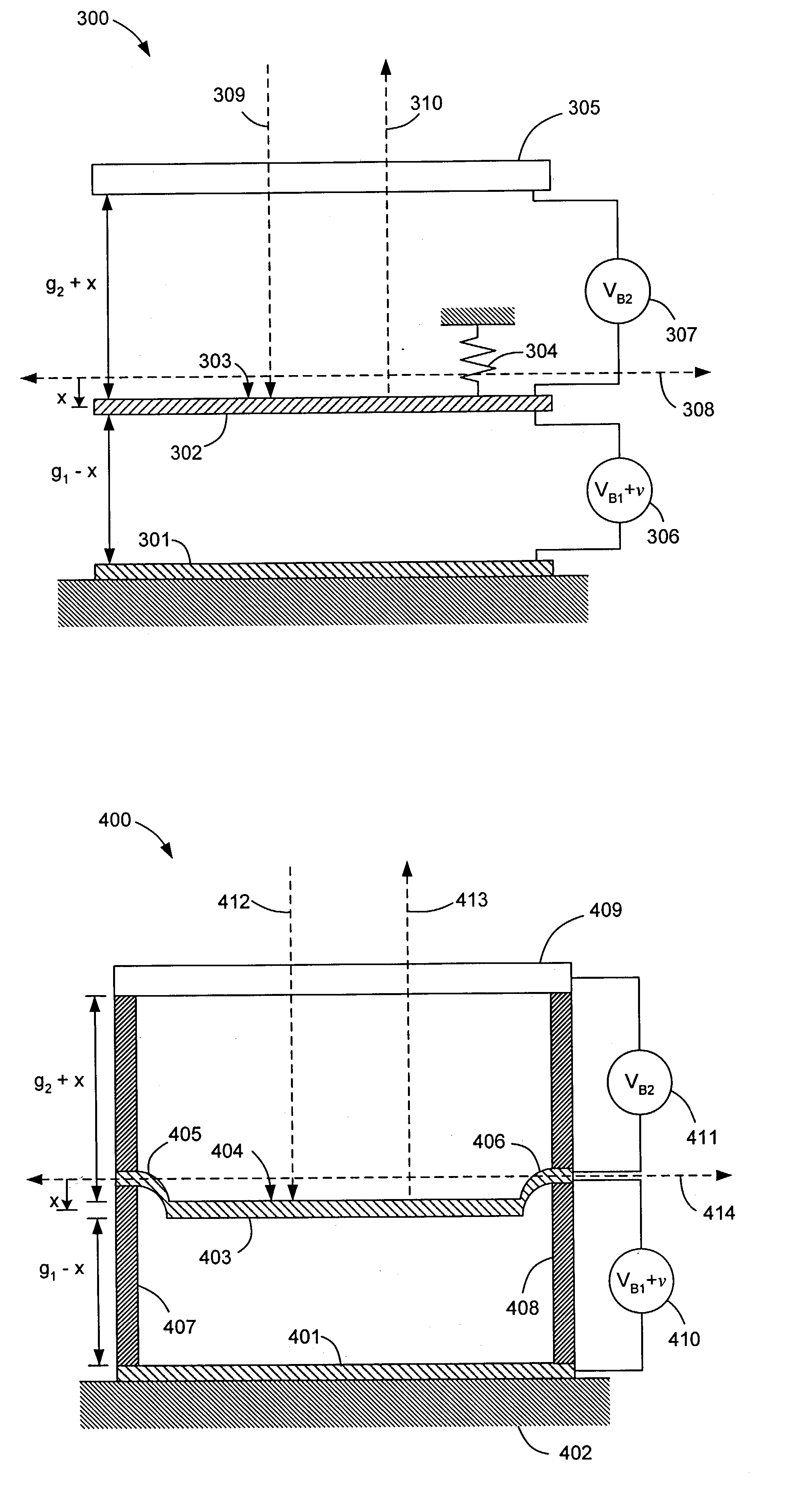
[0022] A MEMS-based electrostatic actuator and actuation method, such as those designed for use in SLMs, is disclosed having three electrodes: a lower electrode, an upper electrode fixed with respect to the lower electrode, and a center electrode suspended between the lower and upper electrodes. A bias voltage is applied between the lower and center electrodes (lower / center pair), and also between the upper and center electrodes (upper / center pair), though not necessarily of the same magnitude. The center electrode is actuable between the lower and upper electrodes when a variable voltage is applied between one of the two electrode pairs. While not intended to be limiting, the driver voltage is preferably applied between the lower / center pair, primarily in order to allow positioning of driver electronics below and adjacent the lower electrode, as will be discussed herein. It is also notable that the fixed relationship between the upper and lower electrodes indicates that, at least d...


PUM

PropertyMeasurementUnit
voltageaaaaaaaaaa
drive voltageaaaaaaaaaa
sizesaaaaaaaaaa

Abstract

A MEMS SLM and an electrostatic actuator associated with a pixel in an SLM. The actuator has three electrodes: a lower electrode; an upper electrode fixed with respect to the lower electrode; and a center electrode suspended and actuable between the upper and lower electrodes. The center electrode is capable of resiliently-biasing to restore the center electrode to a non-actuated first equilibrium position, and a mirror is operably connected to the center electrode. A first voltage source provides a first bias voltage across the lower and center electrodes and a second voltage source provides a second bias voltage across the upper and center electrodes, with the first and second bias voltages determining the non-actuated first equilibrium position of the center electrode. A third voltage source provides a variable driver voltage across one of the lower / center and upper / center electrode pairs in series with the corresponding first or second bias voltage, to actuate the center electrode to a dynamic second equilibrium position.

Description

I. CLAIM OF PRIORITY IN PROVISIONAL APPLICATION[0001] This application claims priority in provisional application filed on Jan. 9, 2002, entitled "Differentially-driven MEMS SLM" serial No. 60 / 347,300, by Eddy A. Stappaerts.II. FIELD OF THE INVENTION[0003] The present invention relates to spatial light modulators. The invention relates more particularly to low voltage MEMS-based (micromachined electromechanical system) electrostatic actuators and MEMS-based phase spatial light modulators utilizing the same.III. BACKGROUND OF THE INVENTION[0004] The use of high performance spatial light modulators (SLMs) for military and commercial adaptive optics (AO) applications is increasing rapidly. Examples are free-space communication systems corrected for atmospheric distortion, compensated imaging systems, secure holographic storage systems, optical computers, and various defense applications, among others. Key SLM characteristics are high speed, high phase resolution, large number of pixels...

Claims


Application Information

Patent Timeline
Patent Type & Authority Applications(United States)
IPC IPC(8): G02B26/08
CPCG02B26/0841
Inventor STAPPAERTS, EDDY A.
Owner LAWRENCE LIVERMORE NAT SECURITY LLC
Why Eureka
Try Eureka