
Method and apparatus for measuring magnetic field strengths

Inactive Publication Date: 2004-01-22
DANMAG
View PDF0 Cites 24 Cited by
  • Summary
  • Abstract
  • Description
  • Claims
  • Application Information

AI Technical Summary

Benefits of technology

[0037] In the previous section it was assumed that the rotating electric field was turned on and off sufficiently slowly that the Rydberg atoms propagate adiabatically through quasi-stationary states except for very small values of B.sub.eff. In the quantum interference methods to be discussed it is assumed that the rotating field is turned on and off suddenly. Since the Rydberg atoms are unable to follow the sudden switching, they are brought into non-stationary states that develop non-trivially in time. The Rabi method uses one field pulse, whereas the Ramsey method uses two pulses with a given period in between. While the near-adiabatic transformation method leads to a simple resonance curve in the form of a dip in the probability for adiabatic transformation, both the Rabi and the Ramsey methods lead to rich oscillatory structures which allow the frequency of the resonance to be determined with very high precision.
[0048] The Ramsey curves 41, 42, 43, 44 in FIG. 4 and 51, 52, 53, 54 in FIG. 5 have T=8 .mu.s and the same values of B, .omega..sub.S / 2.pi.f.sub.-0, and r as the Rabi curves of FIG. 3. The curves 41, 42, 43, 44 were obtained for fixed T, and the lower curves 42, 43, 44 show the effect of averaging .tau. with .sigma. / .tau.=0.5%, 1.0%, and 1.5%. The curves 51, 52, 53, 54 were obtained for fixed .tau., and the lower curves 52, 53, 54 show the effect of averaging T with .sigma. / T=1%, 2%, and 3%.
[0050] The Rabi oscillations depend on the effective magnetic field strength, Buffs in the rotating frame through the combined electric and magnetic fields, .omega..sub.R. The period of the oscillations as a function of frequency therefore vary with detuning relative to the resonance frequency f.sub.0. This is seen clearly in FIG. 3. Since the period depends not only on B.sub.eff but also on the electric field, measuring the period does not give direct information on B.sub.eff. However, the oscillations are symmetrically distributed around the frequency f.sub.0 for which B.sub.eff=0, and they therefore assist in determining the precise value of f.sub.0.

Problems solved by technology

Of these three parameters, one can be measured precisely in absolute units, only if the other two are known, which is a disadvantage of the method.

Method used


Image

  • Method and apparatus for measuring magnetic field strengths
  • Method and apparatus for measuring magnetic field strengths
  • Method and apparatus for measuring magnetic field strengths

Examples


Embodiment Construction

[0008] According to the invention this object is achieved by a method for measuring the strength of a magnetic field wherein said strength of said magnetic field is related to the frequency of a rotating or oscillating electric field and said frequency of said rotating or oscillating field is determined.

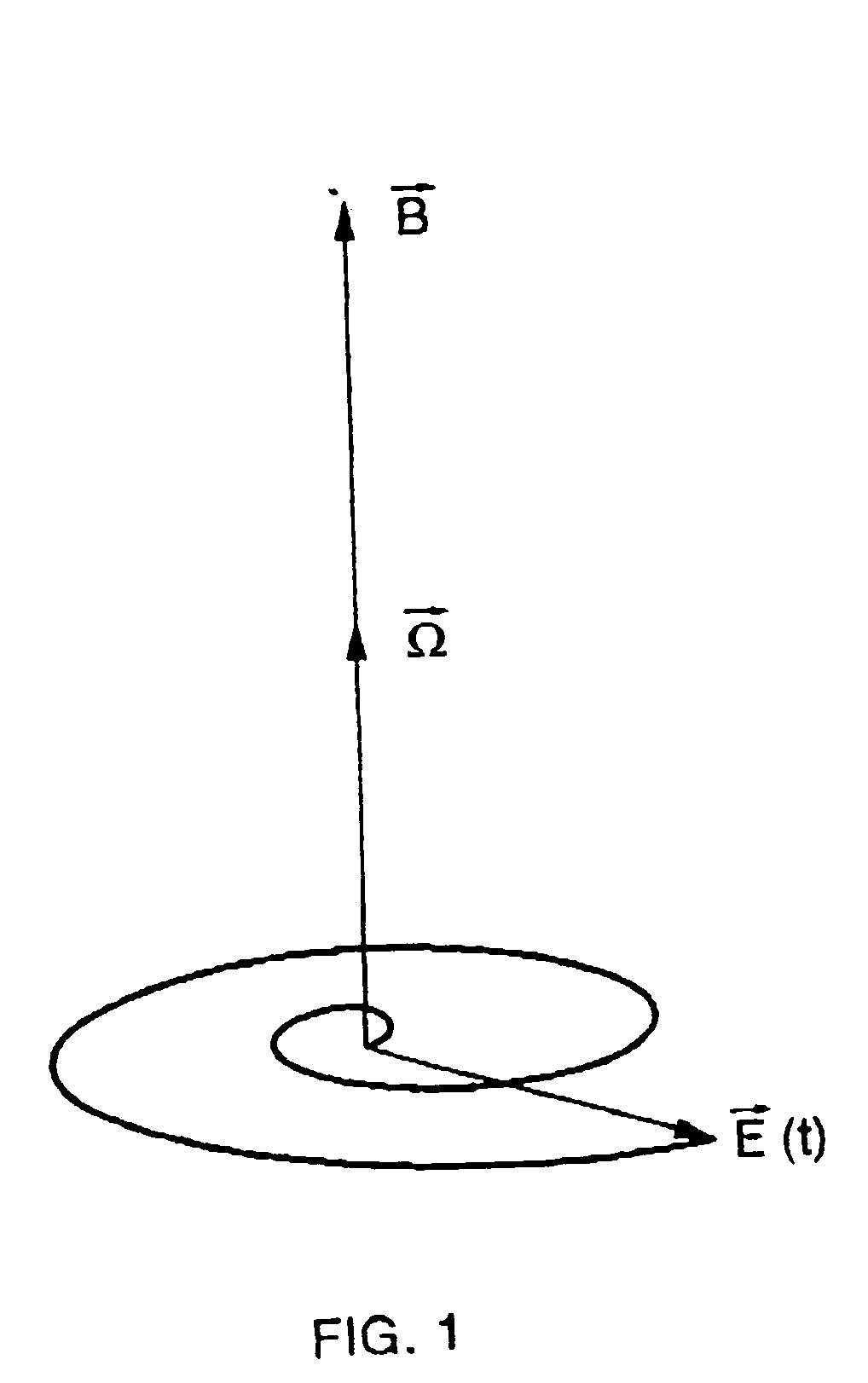
[0009] The invention is based on a new resonance phenomenon, which is called atomic pseudo-spin resonance, ApSR. It takes advantage of a particular pseudo-spin vector defined for hydrogenic atomic systems. When compared to the well-known NMR-technique, the ApSR uses the pseudo-spin vector in place of the magnetic moment, and an oscillating electric field in place of an oscillating magnetic field. It allows a magnetic field-strength to be measured directly in units of frequency, . The ratio of resonance frequency to magnetic field-strength equals e / 2m, where e and m are the elementary charge and the reduced electron mass, respectively. This is the Bohr magneton divided by Plancks cons...


PUM


Abstract

The invention is a method and apparatus for measuring the strengths of magnetic fields directly in units of frequency of a rotating or oscillating electric field utilising a novel resonance phenomenon called atomic pseudo-spin resonance, ApSR. The ratio of field to frequency is 2m / e, where m and e are the reduced electron mass and the elementary charge, respectively. The magnetic field-strength is thus tied directly to the best physical standard known at present, the frequency of atomic clocks, and the tie is a fundamental constant of nature known with exceedingly good precision.

Description

1. BACKGROUND OF THE INVENTION[0001] Natural magnetic fields surround the Earth and penetrate deep into its interiour regions. The main sources of these fields are electric currents in the liquid core of the planet and in the ionized regions of its atmosphere, but locally, in the Earths' crust and on the surface, specific sources in the form of nearby minerals of varying magnetic properties can also be important. There is even a weak, but nevertheless detectable, field-component on Earth from the current of the solar wind. The atmospheric magnetic field is important for the structure and physics of the atmosphere, and is therefore essential for life on Earth. Also, navigation on Earth and in space close to Earth still relies strongly on the natural magnetic field. The solar magnetic field powered by the solar wind extends throughout the huge region of the heliosphere, and it may very well prove to have direct and important consequences for the global climate on Earth including the o...

Claims


Application Information

Patent Timeline
Patent Type & Authority Applications(United States)
IPC IPC(8): G01R33/24
CPCG01R33/24
Inventor PEDERSEN, ERIK HORSDAL
Owner DANMAG
Learn More