Image pickup lens, image pickup unit and portable terminal

a technology of image pickup and portable terminal, which is applied in the field of image pickup lens, image pickup unit and portable terminal, can solve the problems of difficult to obtain the telecentric characteristic of light flux on the image side, the position of an image point of the whole image pickup lens changes with the temperature, and the image pickup lens is not suitable for the shortening of a total lens length

Inactive Publication Date: 2004-01-22
KONICA CORP
View PDF2 Cites 52 Cited by
  • Summary
  • Abstract
  • Description
  • Claims
  • Application Information

AI Technical Summary

Problems solved by technology

However, in the image pickup lens disclosed in the Application No. 2001-75006, though various types aberration are preferably corrected while maintaining the wide angle of view, the image pickup lens is not appropriate to the shortening of a total lens length (that is, a distance from an aperture stop to a focal point on an image side) along an optical axis.
Therefore, it is difficult to obtain the telecentric characteristic of the light flux on the image side.
Therefore, assuming that plastic lenses are used for all lenses of the image pickup lens, a problem has arisen that the position of an image point of the whole image pickup lens changes with the temperature.
Because the saturated water absorption rate of the plastic material is larger than that of the glass material, a non-uniform distribution of absorbed water occurs in the plastic lens due to a rapid change of humidity.
Therefore, the refractive index of the plastic lens cannot be uniformly set, and a preferable image forming performance cannot be obtained.
As described above, though the plastic lens is advantageous to make a miniaturized lightweight image pickup lens at low cost, the plastic lens has a fault that the position of an image point of the lens considerably changes due to a large change of the refractive index of the lens caused by the temperature change.
Also, when the image pickup unit is miniaturized, the miniaturization of the lenses composing the image pickup lens is required, and the curvature radius of each lens necessarily becomes small.
However, as the curvature radius is smaller, the difficulty in the keeping of the manufacturing precision of the lens is increased.
However, the change of the refractive index of the plastic material caused by the temperature change is large.
Therefore, when all lenses of the image pickup lens are formed of the plastic material, a problem has arisen that the position of the image point of the whole image pickup lens changes with the temperature.
This positional change of the image point causes a problem particularly in an image pickup device (so-called pan-focus type image pickup device) on which a solid-state image pickup element having pixels densely arranged is mounted without having an auto-focus mechanism.
When the position of the image point is changed due to the temperature change, a problem has arisen that the quality of the image of the object spaced by the infinite distance or the very short distance is extremely degraded.
To obtain the structure of the image pickup lens described above, when a degree of the design freedom is considered, the triplet lens structure is not adequate, and the image pickup lens having a quadruplet lens structure is required.
Therefore, the structure of five lenses or more is not adequate.

Method used


Image

  • Image pickup lens, image pickup unit and portable terminal
  • Image pickup lens, image pickup unit and portable terminal
  • Image pickup lens, image pickup unit and portable terminal

Examples


example 1

[0167] Lens data is shown in Tables 1, 2 and 3.

1TABLE 1 (Example 1) f = 4.191 mm, fB = 1.795 mm, F = 2.88, 2Y = 5.08 mm Surface No. R (mm) D (mm) Nd .nu.d 1 4.425 1.10 1.58313 59.4 2 -9.128 0.20 stop .infin. 0.20 3 -3.207 1.20 1.53040 56.0 4 -1.092 0.34 5 -0.726 0.86 1.58300 30.0 6 -1.524 0.10 7 2.538 1.14 1.53040 56.0 8 2.712

[0168]

2TABLE 2 Coefficients of aspherical surface Third surface K =9.21940 A4 = -1.90800 .times. 10.sup.-2 A6 =3.78880 .times. 10.sup.-2 A8 = -1.01770 .times. 10.sup.-1 A10 =1.61350 .times. 10.sup.-1 Fourth surface K = -2.43830 .times. 10.sup.-1 A4 = 1.33880 .times. 10.sup.-1 A6 =1.41590 .times. 10.sup.-2 A8 =9.87250 .times. 10.sup.-3 A10 =2.11700 .times. 10.sup.-2 Fifth surface K = -1.91890 A4 = 1.13150 .times. 10.sup.-1 A6 =8.99300 .times. 10.sup.-3 A8 = -3.76430 .times. 10.sup.-3 A10 =6.11200 .times. 10.sup.-3 A12 = -3.26330 .times. 10.sup.-3 Sixth surface K = -3.37000 .times. 10.sup.-1 A4 =8.35040 .times. 10.sup.-2 A6 =2.41350 .times. 10.sup.-2 A8 = -5.1770...

example 2

[0173] Lens data is shown in Tables 5, 6 and 7.

5TABLE 5 (Example 2) f = 4.200 mm, fB = 1.791 mm, F = 2.88, 2Y = 5.08 mm Surface No. R (mm) D (mm) Nd .nu.d 1 3.917 1.10 1.51633 64.1 2 -8.052 0.20 stop .infin. 0.20 3 -3.422 1.20 1.53040 56.0 4 -1.083 0.31 5 -0.732 0.86 1.58300 30.0 6 -1.527 0.10 7 2.426 1.07 1.53040 56.0 8 2.322

[0174]

6TABLE 6 Coefficients of aspherical surface Third surface K = 9.31360 A4 = -3.44480 .times. 10.sup.-2 A6 = 5.08930 .times. 10.sup.-2 A8 = -1.53070 .times. 10.sup.-1 A10 = 1.61750 .times. 10.sup.-1 Fourth surface K = -4.31080 .times. 10.sup.-1 A4 = 1.22030 .times. 10.sup.-1 A6 = -1.44230 .times. 10.sup.-2 A8 = 1.37060 .times. 10.sup.-2 A10 = 9.35930 .times. 10.sup.-3 Fifth surface K = -2.00120 A4 = 1.12270 .times. 10.sup.-1 A6 = 2.28080 .times. 10.sup.-3 A8 = -8.64850 .times. 10.sup.-3 A10 = 7.55610 .times. 10.sup.-3 A12 = -2.07840 .times. 10.sup.-3 Sixth surface K = -6.31350 .times. 10.sup.-1 A4 = 8.67650 .times. 10.sup.-2 A6 = 2.05150 .times. 10.sup.-2 A...

example 3

[0179] Lens data is shown in Tables 9, 10 and 11.

9TABLE 9 (Example 3) f = 5.309 mm, fB = 0.511 mm, F = 2.88, 2Y = 6.48 mm Surface No. R (mm) D (mm) Nd .nu.d stop .infin. 0.00 1 3.227 1.27 1.69680 55.5 2 -87.050 0.44 3 -3.364 1.40 1.52500 56.0 4 -1.626 0.35 5 -1.021 0.90 1.58300 30.0 6 -2.147 0.10 7 2.462 1.10 1.52500 56.0 8 2.283 1.00 9 .infin. 0.30 1.51633 64.1 10 .infin.

[0180]

10TABLE 10 Coefficients of aspherical surface Third surface K = -3.69470 A4 = -2.00408 .times. 10.sup.-2 A6 = 5.93561 .times. 10.sup.-3 A8 = 5.22016 .times. 10.sup.-4 A10 = -2.38137 .times. 10.sup.-4 Fourth surface K = -8.46375 .times. 10.sup.-1 A4 = -2.02564 .times. 10.sup.-2 A6 = 1.62756 .times. 10.sup.-2 A8 = -4.14965 .times. 10.sup.-3 A10 = 6.66591 .times. 10.sup.-4 Fifth surface K = -8.10560 .times. 10.sup.-1 A4 = 6.31710 .times. 10.sup.-2 A6 = 4.14530 .times. 10.sup.-4 A8 = 4.30470 .times. 10.sup.-3 A10 = -2.38210 .times. 10.sup.-3 A12 = 3.81300 .times. 10.sup.-4 Sixth surface K = -4.69690 .times. 10.su...


PUM


Abstract

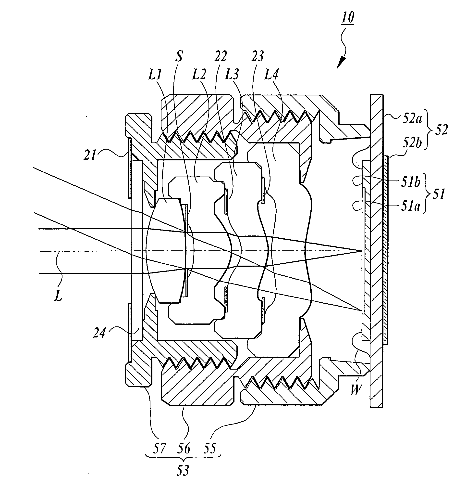
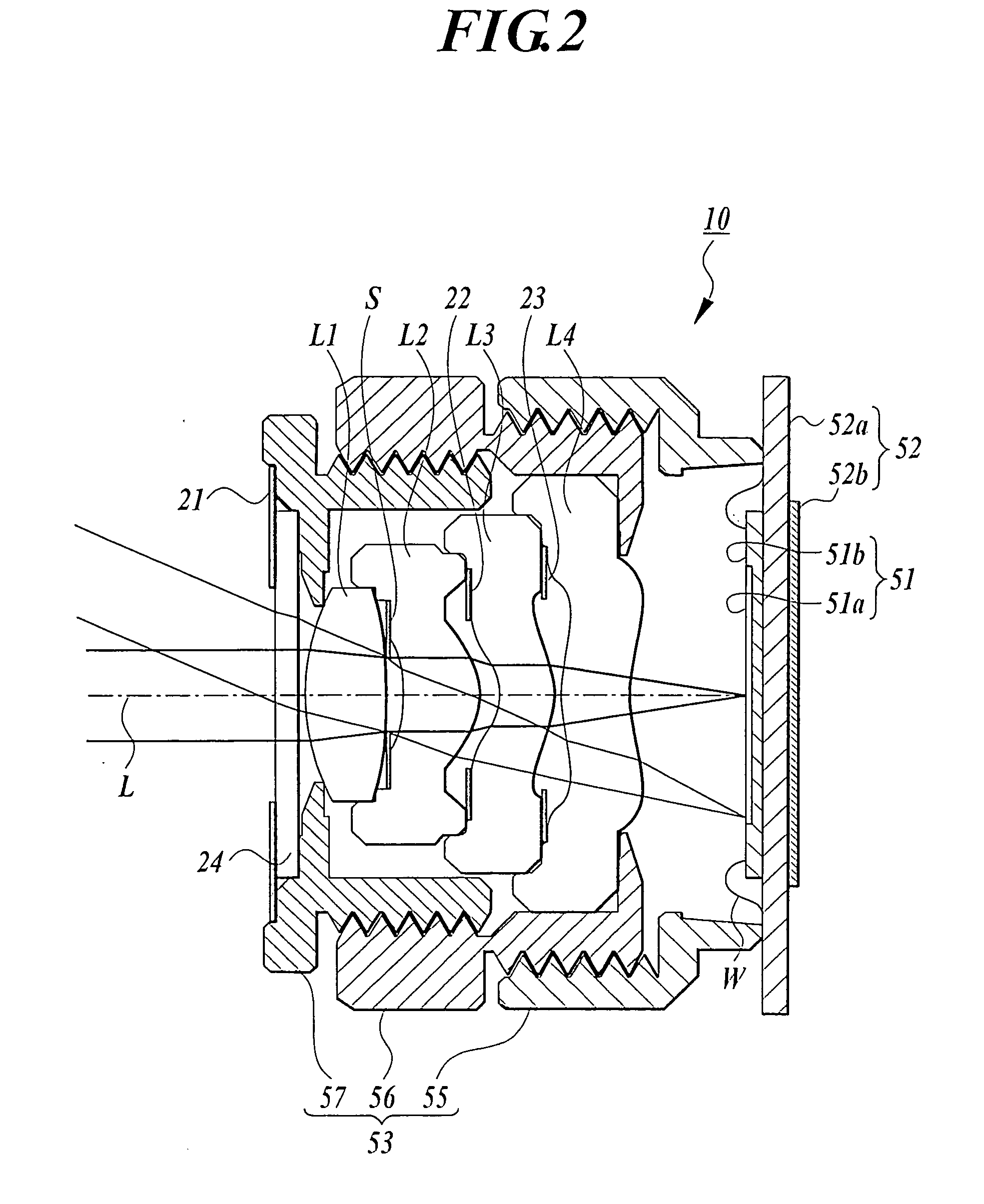
An image pickup lens has four lenses arranged in an order of a first lens, a second lens, a third lens and a fourth lens from an object side. The first lens has positive refractive power and has a convex surface facing toward an object side, the second lens has the positive refractive power, the third lens has negative refractive power and has a concave surface facing toward the object side to be formed in a meniscus shape, and the fourth lens has the positive or negative refractive power and has a convex surface facing toward the object side to be formed in the meniscus shape.

Description

[0001] 1. Field of the Invention[0002] The invention relates to an image pickup lens preferable as an optical system of a solid state pickup element such as a CCD type image sensor or a CMOS type image sensor, an image pickup unit having the image pickup lens, and a portable terminal having the image pickup unit.[0003] 2. Description of Related Art[0004] In recent years, with the heightened performance and the miniaturization of an image pickup device using a solid-state image pickup element such as a CCD (charge coupled device) type image sensor or a CMOS (complementary metal oxide semiconductor) type image sensor, a portable terminal and a personal computer respectively having the image pickup device have spread to users.[0005] Also, with the miniaturization and the dense arrangement of pixels of the element due to the increase of functions in the portable terminal and the personal computer, the further miniaturization of an image pickup lens mounted on the image pickup device is ...

Claims


Application Information

Patent Timeline
Patent Type & Authority Applications(United States)
IPC IPC(8): G02B9/34G02B13/18G02B13/00
CPCG02B13/004G02B9/34G02B13/18
Inventor YAMAGUCHI, SUSUMU
Owner KONICA CORP
Why Eureka
Try Eureka