
Method and apparatus for automated signal integrity checking

a signal integrity and signal technology, applied in the field of simulation, can solve the problems of more complex electronic systems, more peripheral and support technologies, and more complex electronic systems to implement and use electronic systems

Inactive Publication Date: 2004-01-22
AVAGO TECH WIRELESS IP SINGAPORE PTE
View PDF2 Cites 21 Cited by
  • Summary
  • Abstract
  • Description
  • Claims
  • Application Information

AI Technical Summary

Problems solved by technology

As electronic systems have become more sophisticated and complex, peripheral and support technologies have also had to become more sophisticated and complex to implement and use the electronic systems.
As electronic systems have become more complex and include more components, simulation tools have also had to become more complex.
However with millions of components located within these electronic systems, the simulation of components and traces between components is a substantial computational task.
Running a simulation on an integrated circuit with millions of electronic components can exhaust the resources of a supercomputer for hours, months or even years depending on the sophistication of the simulation.
However with millions of electronic components fed by hundreds of millions of wires (traces), simulating cross-coupling is a substantial computational task.
However, implementing these design techniques requires that we first identify each cross-coupling problem and then redesign the integrated circuit or printed circuit board to address the cross-coupling problem.
However once again, the sheer volume of the analysis can be a daunting computational task.
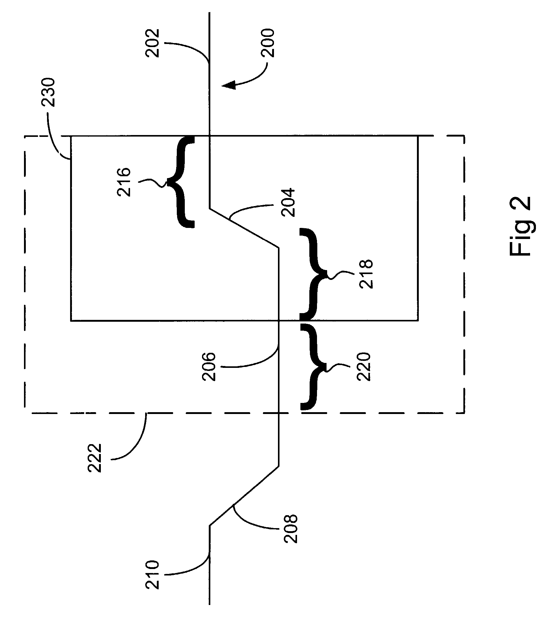
The vulnerability window is a time period when the storage device may produce invalid data if an input to the storage device receives noise (e.g. cross-coupling) during that time period.
Invalid data on a storage element denotes a cross-coupling problem exists.

Method used


Image

  • Method and apparatus for automated signal integrity checking
  • Method and apparatus for automated signal integrity checking
  • Method and apparatus for automated signal integrity checking

Examples


Embodiment Construction

[0023] While the present invention is described herein with reference to illustrative embodiments for particular applications, it should be understood that the invention is not limited thereto. Those having ordinary skill in the art and access to the teachings provided herein will recognize additional modifications, applications, and embodiments within the scope thereof and additional fields in which the present invention would be of significant utility.

[0024] In digital electronic systems implemented in accordance with the teachings of the present invention, data signals traveling on wires or traces are characterized as in a high state (e.g. logical 1) or in a low state (e.g. logical 0). In addition, the signals communicated on traces may transition from a high state to a low state. The transition is characterized as a rising transition when the signal goes from a low state to a high state. The transition is characterized as a falling transition when the signal goes from a high sta...


PUM


Abstract

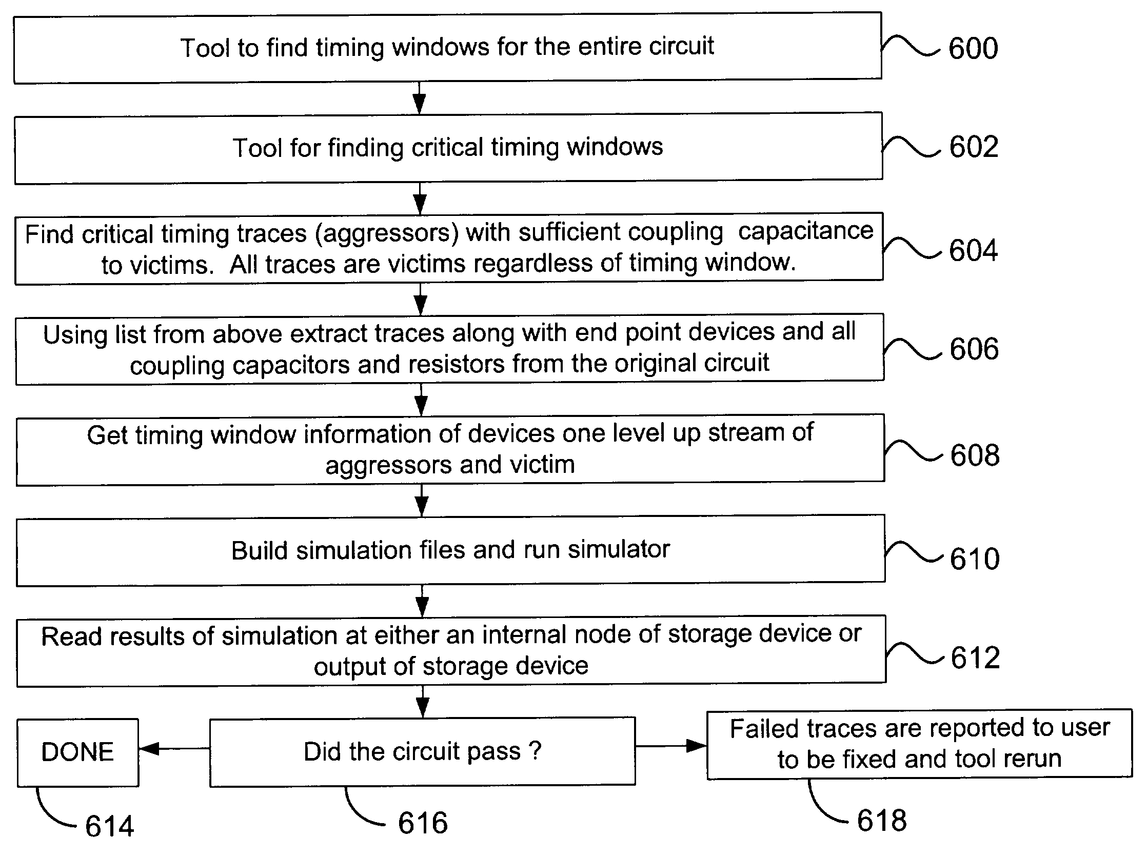
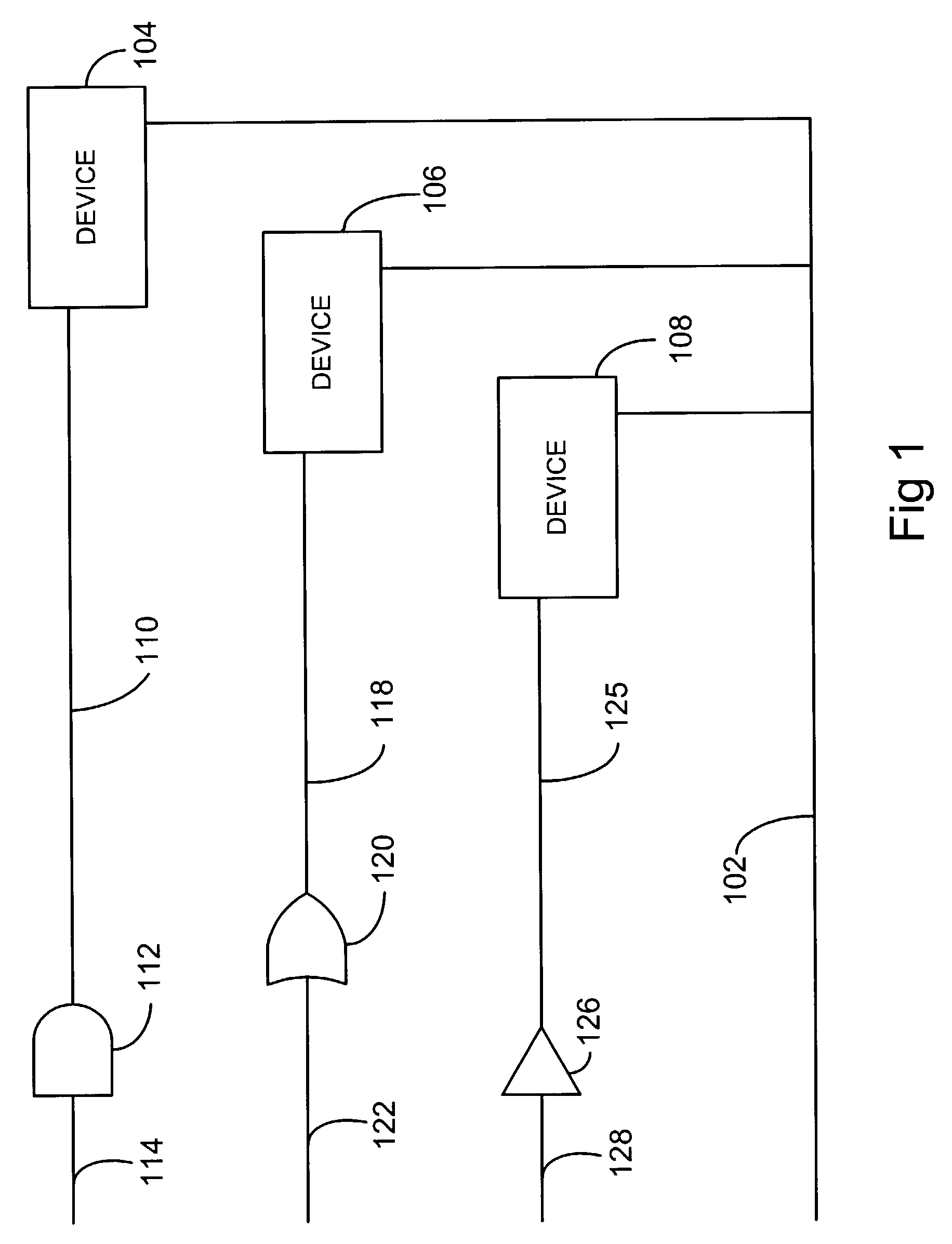
The present invention is directed to a method and apparatus for simulating digital electronic systems. The signal integrity of a digital electronic system is assessed by analyzing traces (e.g. wires between components) for cross coupling. Problem areas are identified by monitoring storage components or output ports of the electronic system. Wires (traces), which carry signal transitions to the storage component or output ports are analyzed and quantified based on timing windows associated with the wires (traces). The clock transitions into a storage device are analyzed and vulnerability windows are identified for the storage device. The vulnerability windows are time periods when cross coupling may occur on a storage device. If a timing window overlaps a vulnerability window the timing window is considered a critical timing window. Devices driving the transition on wires with critical timing windows are then analyzed. Adjustments are made to the parameters of the driving devices to create a worse case scenario. The worse case scenario is simulated and analyzed for cross-coupling.

Description

[0001] This application is related to U.S. application Ser. No. ______ filed ______, which is hereby incorporated by reference in its entirety.[0002] 1. Field of the Invention[0003] This invention relates to simulation. Specifically, the present invention relates to the simulation of electronic systems.[0004] 2. Description of the Related Art[0005] Modern electronic systems have advanced over the last several decades. Electronic systems are now implemented in integrated circuits and on printed circuit boards. Integrated circuits and printed circuit boards that once included thousands of transistors and logic gates now include millions of transistors and logic gates.[0006] As electronic systems have become more sophisticated and complex, peripheral and support technologies have also had to become more sophisticated and complex to implement and use the electronic systems. One area that has seen tremendous advancement is the area of testing and simulation of electronic systems. As thes...

Claims


Application Information

Patent Timeline
Patent Type & Authority Applications(United States)
IPC IPC(8): G06F17/50G06G7/62
CPCG06F17/5036G06F30/367
Inventor LAWRENCE, WILLIAM RICHARDOSTOJIC, FRANCISCO A.LAMBERT, MICHAEL ROGERSMARTIN, ROBERT J.WEBER, EDWARD V.
Owner AVAGO TECH WIRELESS IP SINGAPORE PTE
Learn More