Phase shifters using transmission lines periodically loaded with Barium Strontium Titanate (BST) capacitors

a technology of barium strontium titanate and capacitors, which is applied in the field of phased antenna arrays, can solve the problems of high cost of phase shifters that are currently available, high cost of phase shifters that can be as high as 40% of the total cost of phased arrays, and ferrite phase shifters are typically difficult to manufacture, etc., and achieves low cost and low loss. , the effect of high volum

Inactive Publication Date: 2004-01-29
RGT UNIV OF CALIFORNIA
View PDF20 Cites 15 Cited by
  • Summary
  • Abstract
  • Description
  • Claims
  • Application Information

AI Technical Summary

Benefits of technology

[0013] By way of example, and not of limitation, a phase shifter according to the present invention employs thin film BST capacitors for periodically loading the transmission line as opposed to conventional continuous loading. The BST thin films can be deposited using RF sputtering, which is less expensive in comparison with semiconductor epitaxy. Moreover, the BST thin film phase shifter circuits may be manufactured using the high volume, low cost monolithic fabrication techniques developed by the IC industry. These aspects of the invention allow the creation of phase shifters at a fraction of the cost of currently available ferrite / semiconductor phase shifters.
[0024] Another object of the invention is to provide transmission lines that are fabricated on low dielectric constant substrates and which have low conductor losses.

Problems solved by technology

A disadvantage of using a phased array, however, is that that each radiating element requires its own phase shifter, and high performance phase shifters that are currently available are expensive.
In fact, the cost of the phase shifters can be as high as 40% of the total cost of the phased array.
Ferrite phase shifters are typically difficult to manufacture, however, and hence tend to be expensive.
Another disadvantage to the use of ferrite phase shifters is that they are exceedingly slow to respond to control signals, thus making them unsuitable for use in applications requiring rapid beam scanning.
On the other hand, faster response can be achieved by utilizing semiconductor device phase shifters, but semiconductor phase shifters tend to suffer from high losses at microwave and millimeter wave frequencies, and have limited power-handling capability.
This approach has several limitations, however, including: (1) the amount of capacitive loading due to the ferroelectric film cannot be easily varied to optimize phase shifter performance; (2) conductor losses are high in this structure due to the high dielectric constant of the ferroelectric film on which the transmission lines are fabricated; (3) the tunability of the film is not efficiently utilized; and (4) the control voltages required for this approach tend to be very high.

Method used


Image

  • Phase shifters using transmission lines periodically loaded with Barium Strontium Titanate (BST) capacitors
  • Phase shifters using transmission lines periodically loaded with Barium Strontium Titanate (BST) capacitors
  • Phase shifters using transmission lines periodically loaded with Barium Strontium Titanate (BST) capacitors

Examples


Embodiment Construction

[0039] Referring more specifically to the drawings, for illustrative purposes the present invention is described with reference to FIG. 1 through FIG. 8. It will be appreciated that the apparatus may vary as to configuration and as to details of the parts, and that the method may vary as to the specific steps and sequence, without departing from the basic concepts as disclosed herein.

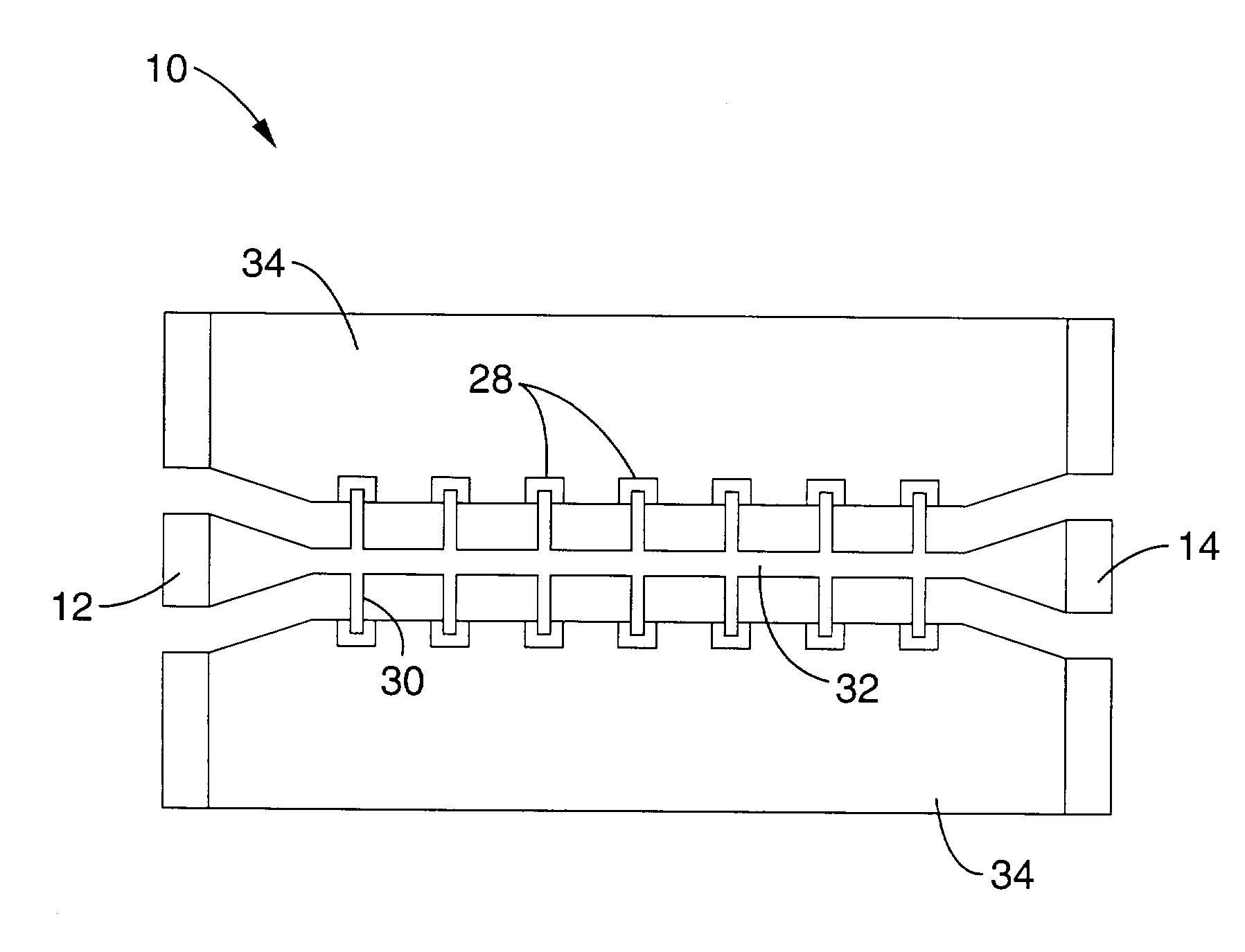
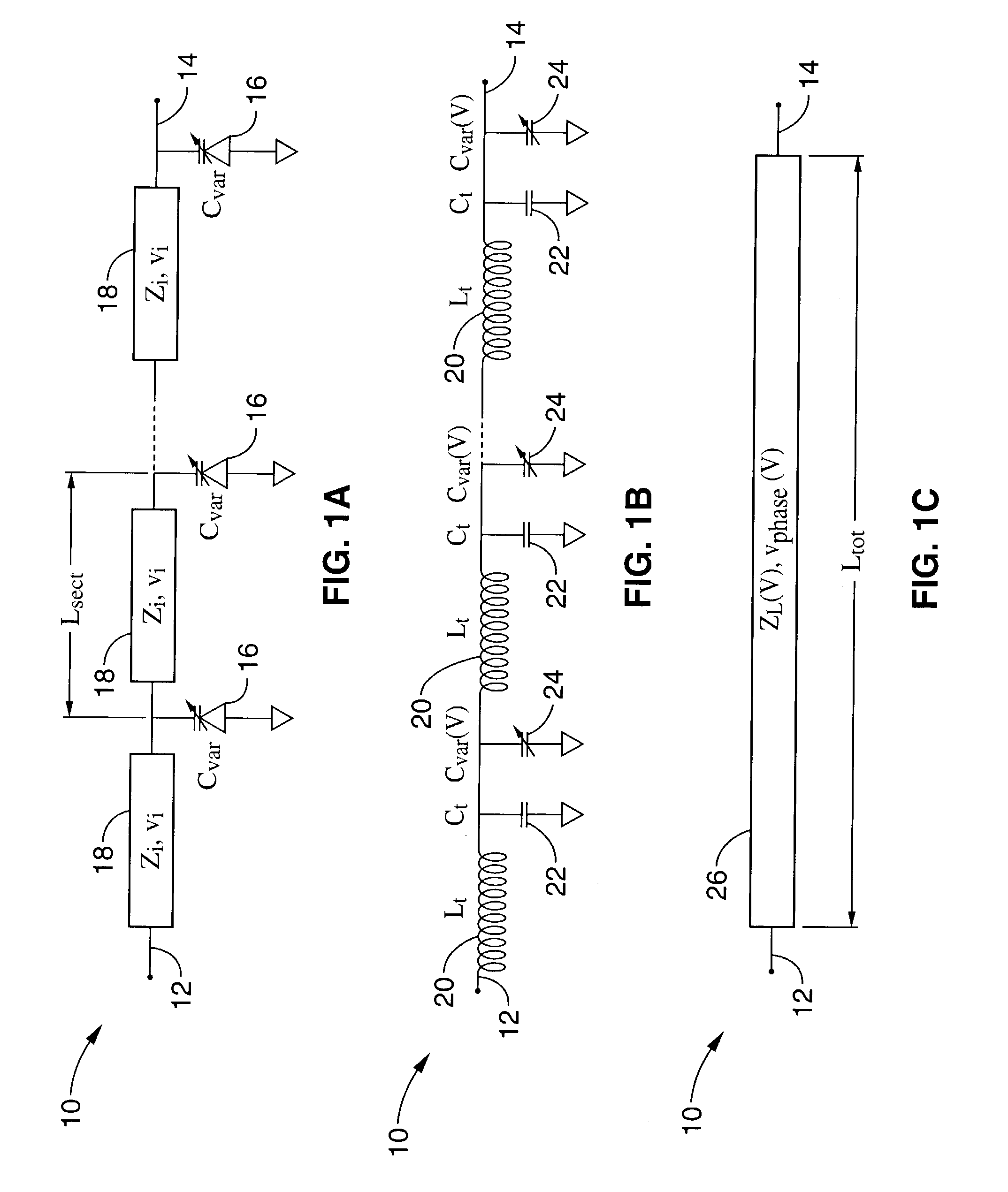
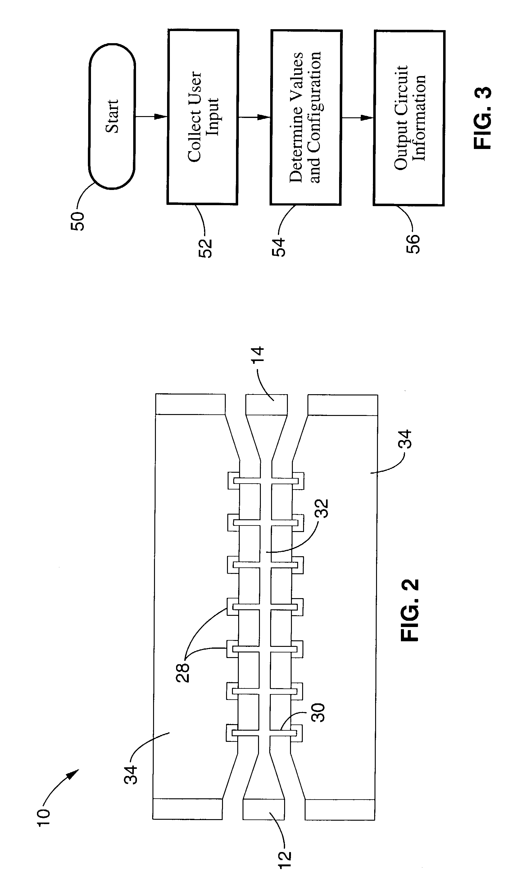
[0040] Referring first to FIG. 1A, a periodically loaded phase shifter 10 according to the present invention is shown schematically. In the embodiment of FIG. 1A, the invention comprises a high impedance transmission line with an input 12 and an output 14, between which are periodically positioned thin film Barium Strontium Titanate (BST) capacitors 16 with spacing L.sub.sect that divide the transmission line into transmission line segments 18.

[0041] For frequencies significantly less than the Bragg frequency, this structure behaves as a synthetic transmission line having an equivalent circuit as shown ...


PUM


Abstract

A phase shifter, such as for use in phased antenna arrays, comprising thin film BST capacitors periodically loading a transmission line. The BST thin films can be deposited using RF sputtering on a variety of substrates, and the capacitors can be of a parallel plate configuration or of an interdigitated configuration. An aspect of the invention additionally provides for the use of periodically distributed lumped-element inductors comprising the transmission line. A further aspect provides for programmatic determination of circuit design and configuration parameters based on the input of desired characteristics and materials for the phase shifter.

Description

CROSS-REFERENCE TO RELATED APPLICATIONS[0001] This application is a continuation of U.S. application Ser. No. 09 / 721,435 filed on Nov. 22, 2000, now U.S. Pat. No. ______, which claims priority from U.S. provisional application serial No. 60 / 167,469 filed on Nov. 24, 1999, incorporated herein by reference.INCORPORATION-BY-REFERENCE OF MATERIAL SUBMITTED ON A COMPACT DISC[0003] Not ApplicableBACKGROUND OF THE INVENTION[0004] 1. Field of the Invention[0005] This invention pertains generally to phased antenna arrays, and more particularly to techniques for loading a associated transmission line to create a phased array.[0006] 2. Description of the Background Art[0007] Phased array antennas are used in a number of applications, including both terrestrial and airborne radar, and satellite and mobile communications, where fast beam scanning is required or where mechanical rotation of the antenna is not practical and / or desirable. Antenna arrays typically comprise several radiating elements...

Claims


Application Information

Patent Timeline
Patent Type & Authority Applications(United States)
IPC IPC(8): H01P1/18
CPCH01P1/181
Inventor NAGRA, AMIT S.YORK, ROBERT A.
Owner RGT UNIV OF CALIFORNIA
Why Eureka
Try Eureka