Device for loading and unloading optical workpieces

a technology for optical workpieces and devices, applied in the direction of grinding drives, manufacturing tools, arms, etc., can solve the problems of workpieces being thrown off, no influence facility, and high setup and adjustment costs of cam-controlled loading systems

Inactive Publication Date: 2004-02-19
SATISLOH GMBH
View PDF9 Cites 13 Cited by
  • Summary
  • Abstract
  • Description
  • Claims
  • Application Information

AI Technical Summary

Benefits of technology

[0012] Thus an essential feature of the invention is the use of a special spindle equipped with several overlaying degrees of movement freedom, the movement processes of which can be freely programmed, preferably independently of the control of the machining processes being performed on the lens machine. This spindle guides and controls in a compact, simple and stable manner all movements of the loading arm i.e. both its 
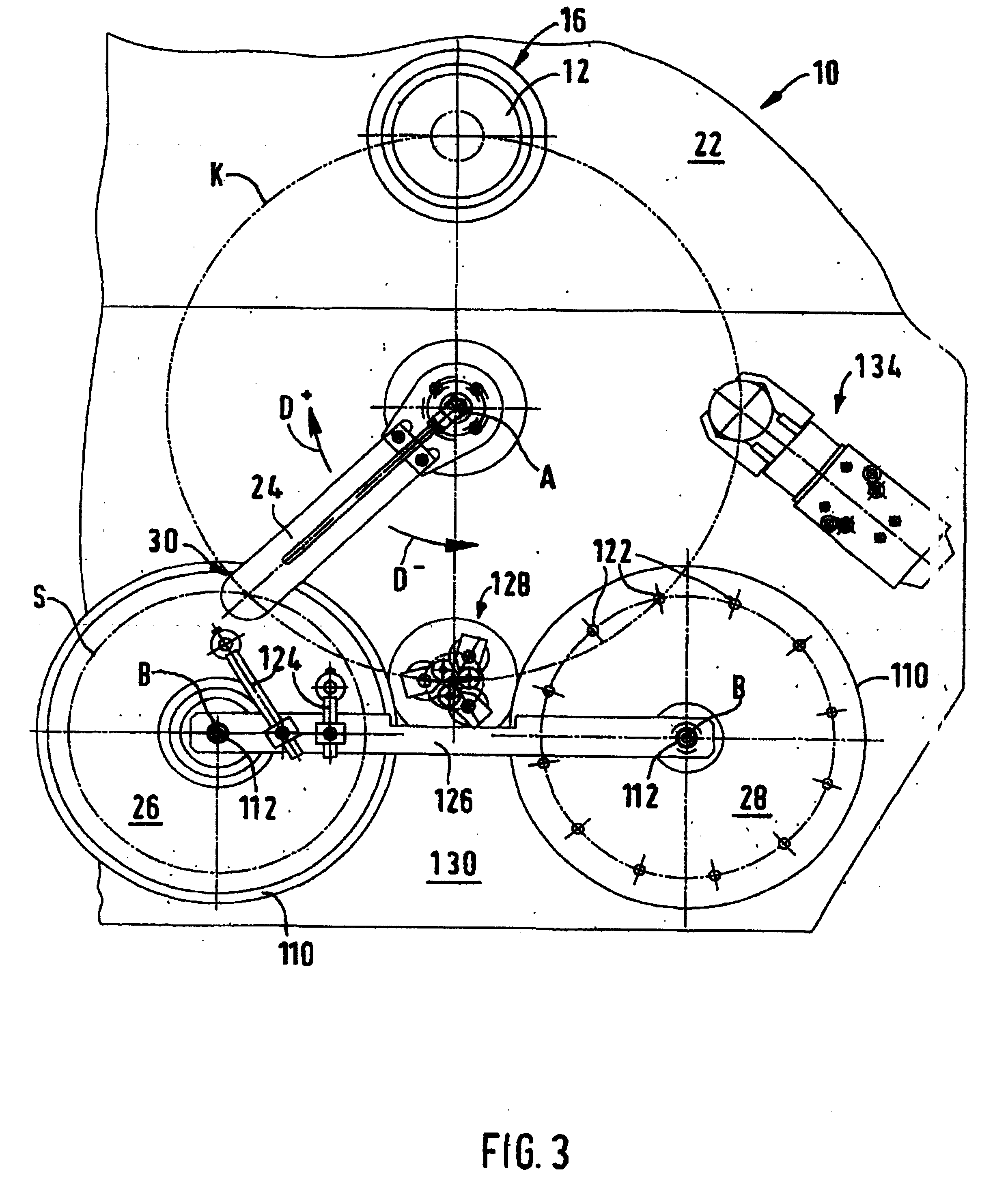
stroke and its rotation movements, without end-of-travel stops being required. In this way the loading arm can approach any intermediate positions at which the device can be fitted with equipment for additional work processes such as precentring, turning or rotating, measuring or washing of the lens. As the loading arm in each direction can be guided over any long or short swivel or stroke movements, all movement processes can be performed with optimum travel and hence time. A spindle which can be used for the purposes of the invention is available commercially under the name "Ball Screw Spline" type BNS from the company THK Co. Limited, Tokyo, Japan. Finally in this connection it should also be stated that the device provided on the loading arm for picking up and depositing workpieces can for example be a vacuum-operated suction element adjustable in height to pick up lenses of different thicknesses against spring force, or a gripper or clamping element driven by compressed air.
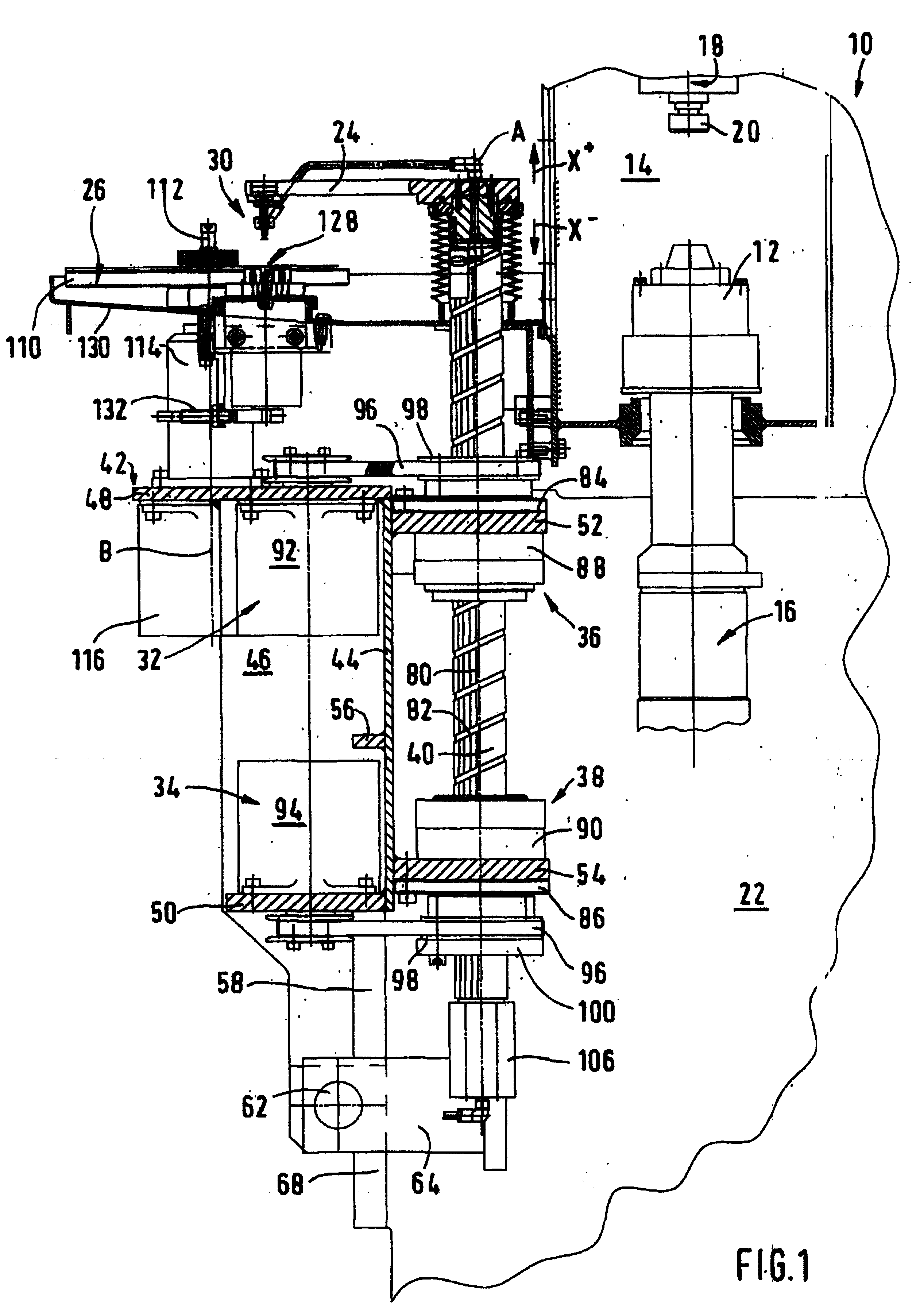
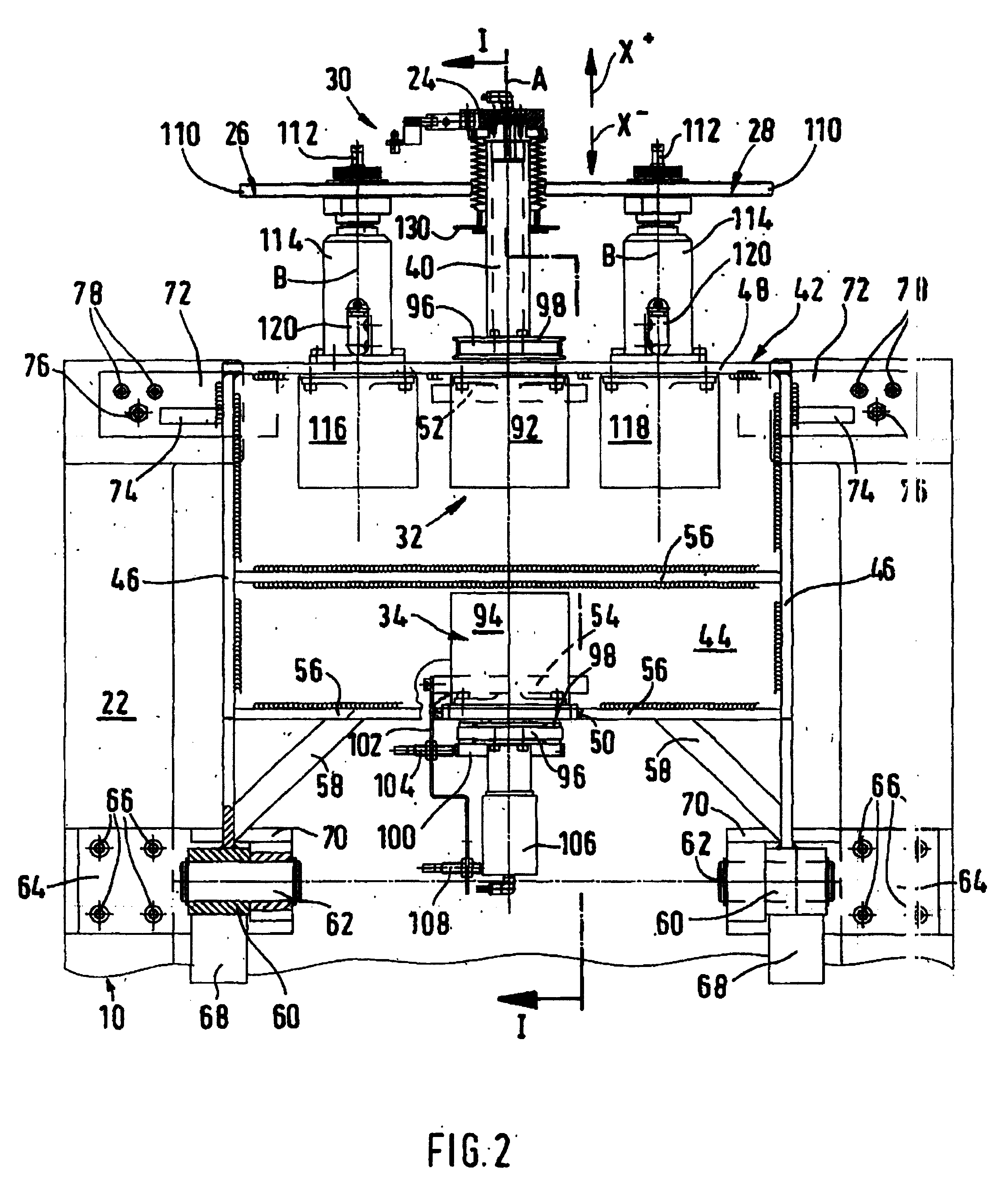
[0013] In an advantageous embodiment of the invention, the spindle with the loading arm, its drive elements and guide elements is attached to a frame which as a self-contained system carrier can dock on the lens machine in a defined position to the workpiece spindle of the lens machine so that the workpiece spindle of the lens machine lies on a swivel circle of the loading arm device. Thus the device can be used as a loading system on any lens machine e.g. fine grinding, polishing, centring or lens edge machining apparatus, even by subsequent fitting. The frame of the invention is there preferably docked on the front side of the lens machine concerned and as a self-contained system carrier can carry or contain all mechanical elements such as also the electronic controls, the operating and display elements (keyboard / screen) and the pneumatics for the device provided on the loading arm for picking up and depositing workpieces. The frame of the device can in a compact construction also have a cylindrical metal sleeve which holds the nut elements according to the invention and protects these against soiling.
[0014] In a further development of the inventive concept, the frame can dock on the lens machine at its lower end via swivel pins and at its upper end via screws and stops which can be adjusted to achieve in a simple manner the axial parallelity between the spindle and the workpiece spindle of the lens machine. As a result after release of the screws the device can be swivelled away to the front whereby e.g. the workpiece spindle of the lens machine is easily accessible for maintenance or repair purposes without hindrance from the device. Alternatively or in addition the frame can also be attached swivelling to the side on the lens machine. Here also adjustable stops and screws can be provided which serve to set the rotary axis distance from the spindle and workpiece spindle.
[0016] In the further development of the invention at the lower end of the totally hollow spindle can be applied a rotary passage through which a vacuum can be applied and / or compressed air supplied to the device of the loading arm. By using the spindle itself as a supply or guide element, the pneumatic pressure can easily be applied to the loading arm device.
[0017] In an advantageous refinement of the invention, on the frame of the device are preferably fitted two magazines for blanks and finished workpieces, the collection and deposit positions of which are on the swivel circle of the loading arm device. The workpieces to be processed or already processed are stored in these magazines so that they can be guided into the relevant collection position or from the deposit position. Preferably the two magazines are rotatable or where applicable exchangeable plate magazines which are symmetrically arranged at the side and--viewed from the front--in front of the spindle, and the rotary axes of which are aligned parallel to the spindle and allocated to each of which is a freely programmable and indexable drive attached to the frame. Thus advantageously there is a good adaptation facility to different workpiece sizes and geometries. As an alternative to the magazine, according to the relevant requirements, a conveyor belt for recipe or lens transport cases can be arranged in relation to the swivel circle of the loading arm device such that by means of the loading arm device, blanks and finished workpieces can be collected from or deposited in correspondingly positioned boxes by means of the conveyor belt.

Problems solved by technology

Automatic loading systems for lens machines are becoming increasingly important because of rising personnel costs.
Such cam-controlled loading systems require great expense in set up and adjustment, offer no facility for influencing the speed of the movement--which is very important with different workpiece weights--and can only approach established, unchanging loading and unloading positions.
Because of the compressibility of compressed air and the stick-slip effect occurring on the pneumatic cylinders, these systems have disadvantages.
In these systems the force with which the loading system is set in movement can be restricted relatively simply by restricting the pressure of compressed air, but difficulties occur with an external movement restriction of the loading arm.
When this restriction is not present, namely very rapid swivel or linear movements result which lead either to the workpieces being flung off or at least displaced and hence to a change in workpiece position.
Furthermore in pneumatically operated loading systems the stops shift due to wear and / or vibration.
This is particularly critical when loading large delicate workpieces.
To summarise it can be found that the precision and reliability of the workpiece insertion using such loading systems are relatively low.
In addition, such systems can also approach only a few established positions of the loading arm.
This design is indeed flexible and works relatively precisely in position, but large masses must be moved over long distances, leading to relatively long change times. Also the CNC axis can only be used for the feed process when the actual machining processes on the lens machine have previously been completed.
A prepositioning of the optical lens to be machined close to the chuck of the workpiece spindle during machining of another lens is not possible.
In addition the longer linear axes necessary cause a considerable increase in production costs of such lens machines and also lead to larger and hence heavier machines.

Method used


Image

  • Device for loading and unloading optical workpieces
  • Device for loading and unloading optical workpieces
  • Device for loading and unloading optical workpieces

Examples


Embodiment Construction

[0011] According to the invention in a device for loading and unloading optical workpieces for a lens machine with a loading arm driven swivellable about an axis, which arm can swivel in controlled movement processes between a workpiece magazine and the machining station on the lens machine and at its outer end has a device for picking up and depositing workpieces, the swivel axis of the loading arm is the centre axis of a spindle rotating in both directions of rotation and drivable mobile in linear strokes in both axial directions by drive elements and guided rotatably and displaceably in guide elements, on which spindle is attached the loading arm, where the spindle is designed both as a splined shaft and as a threaded spindle and is guided by two rotatably mounted, fixed location nut elements forming the guide elements, of which one nut element engages with the splined shaft and the other nut element with the threaded spindle, where the nut elements can be driven individually or ...


PUM

PropertyMeasurementUnit
diameteraaaaaaaaaa
diameteraaaaaaaaaa
vacuumaaaaaaaaaa

Abstract

The invention relates to a device for loading and unloading optical workpieces, for an optical machine. Said device comprises a loading arm (24) which is pivotally driven about an axis (A) and is pivoted in controlled movement sequences on the optical machine between a workpiece magazine (26, 28) and the operating position. The outer end of the loading arm is provided with a device (30) for receiving and placing workpieces. According to the invention, the swivelling axis of the loading arm is the central axis of a spindle (40) which rotates in both directions of rotation (D<+>, X<->) and which can be driven linearly in a lifting motion in both axial directions (X<+>, X<->) by means of drive elements, as well as guided in guide elements in a rotating and displacing manner. The loading arm (24) is fixed to the spindle.

Description

TECHNICAL AREA[0001] The present invention relates, according to the preamble of claim 1, to a device for loading and unloading of optical workpieces, in particular optical lenses, for a lens machine with a loading arms driven swivellable about an axis which in controlled movement processes swivels between a workpiece magazine and the processing station on the lens machine and at its outer end is fitted with a device for picking up and depositing workpieces. Although the description below discusses only the loading or unloading of workpieces, the device is however equally suitable for tool changing.STATE OF THE ART[0002] Automatic loading systems for lens machines are becoming increasingly important because of rising personnel costs. Such loading systems have to take into account a wide range of workpieces, high accuracy requirements and small batch sizes. According to the state of the art there are three different construction concepts, namely (1) devices with cam-controlled loadin...

Claims


Application Information

Patent Timeline
Patent Type & Authority Applications(United States)
IPC IPC(8): B23Q7/02B23Q7/10B24B9/14B24B13/00B24B41/00B25J18/04
CPCB23Q7/02B23Q7/10B24B9/146Y10T82/2514B24B41/005B25J18/04B24B13/0031
Inventor DIEHL, JOACHIMGROH, HERBERTBECKER, BERND
Owner SATISLOH GMBH
Why Eureka
Try Eureka