
Heating crucible and deposition apparatus using the same

a technology of vacuum deposition and crucible, which is applied in the direction of sublimation, electric/magnetic/electromagnetic heating, and separation processes, etc., can solve the problems of reducing the evenness of the deposited film, hindering mass production, and vaporizing organic compounds in lumps

Active Publication Date: 2004-02-26
SAMSUNG DISPLAY CO LTD
View PDF15 Cites 57 Cited by
  • Summary
  • Abstract
  • Description
  • Claims
  • Application Information

AI Technical Summary

Benefits of technology

[0017] Additional aspects and / or advantages of the invention will be set forth in part in the description which follows and, in part, will be obvious from the description, or may be learned by practice of the invention.

Problems solved by technology

While it is preferable to have the organic compound vaporize into molecules during a deposition operation, a sudden vaporization may occur within the organic compound during the heating, resulting in the organic compound being vaporized in lumps.
This problem continuously occurs unless the deposition mask is replaced, thus hindering a mass production.
Also, the deposition material lump may be attached to the substrate, which decreases the evenness of a deposited film.
Furthermore, where a part of an organic compound lump is attached to a nozzle, the organic compound lump is continuously deposited and grown inside the nozzle, consequently blocking the nozzle of the deposition apparatus.
However, the net-type curtain installed on the opening in the heating crucible prevents smooth heat conduction from a heater, such that a foreign material first vaporized from the heating crucible and then deposited on the net curtain is not smoothly vaporized.
In addition, it is difficult to install the net curtain within the heating crucible.
Since an organic compound is heated by a heater installed over an outer circumferential surface of the disclosed heating crucible, the organic compound is not evenly heated.
In addition, the organic compound cannot vaporize uniformly from the entire portion of the crucible.

Method used


Image

  • Heating crucible and deposition apparatus using the same
  • Heating crucible and deposition apparatus using the same
  • Heating crucible and deposition apparatus using the same

Examples


Embodiment Construction

[0029] Reference will now be made in detail to the present preferred embodiments of the present invention, examples of which are illustrated in the accompanying drawings, wherein like reference numerals refer to the like elements throughout. The embodiments are described below in order to explain the present invention by referring to the figures.

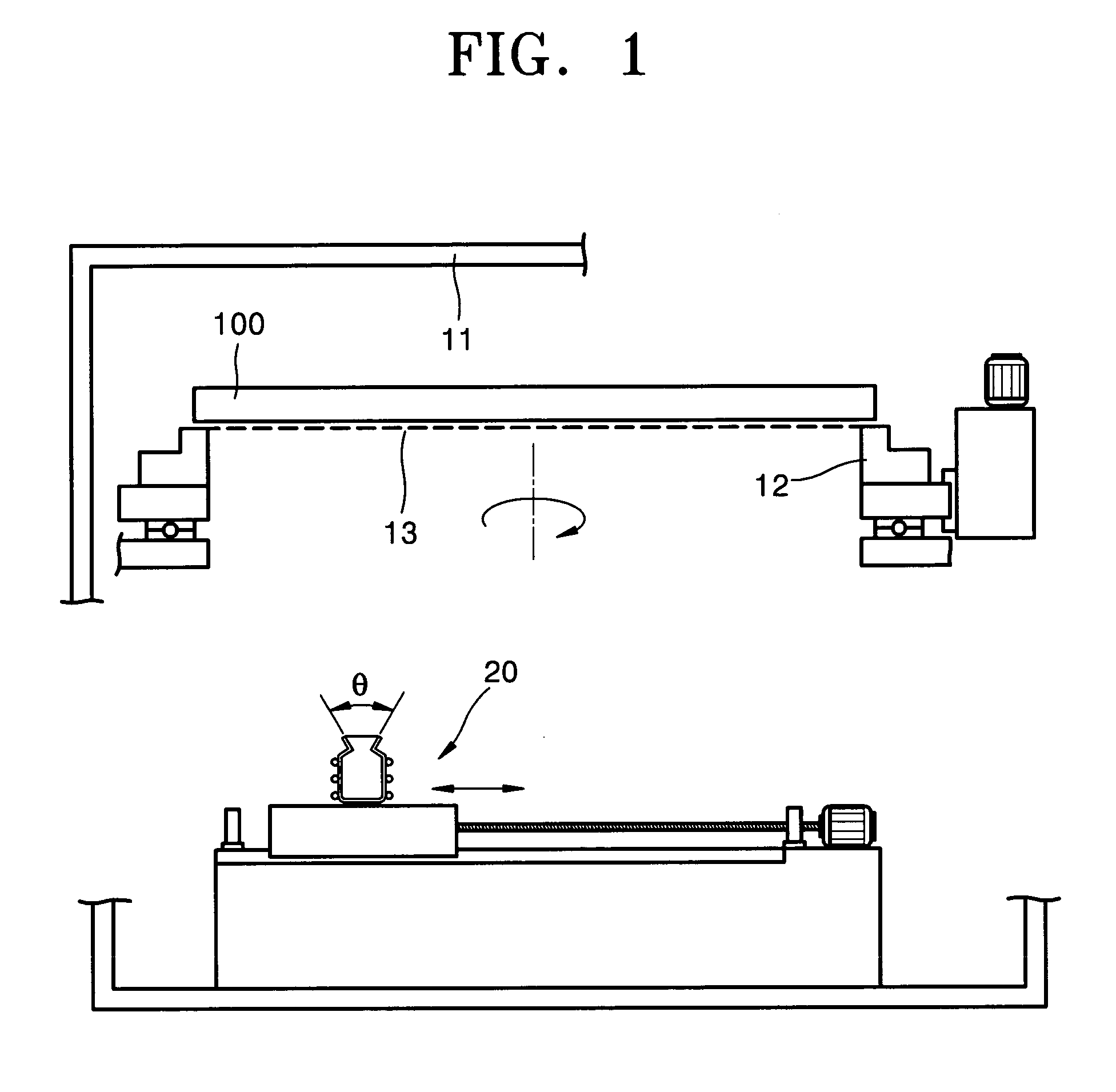
[0030] FIG. 1 shows a vacuum deposition apparatus according to an embodiment of the present invention. The vacuum deposition apparatus includes a vacuum chamber 11, a substrate support 12 that is installed within the chamber 11 to support a deposition substrate 100, a deposition mask 13 that is closely attached to the substrate 100 and has, for example, a pattern of slots, and a heating crucible 20 that is installed opposite to the substrate 100 so as to position the deposition mask 13 between the heating crucible 20 and the substrate 100.

[0031] The substrate support 12 supports an edge of the substrate 100 so as to have a surface of the sub...


PUM

PropertyMeasurementUnit
Temperatureaaaaaaaaaa
Pressureaaaaaaaaaa
Radiusaaaaaaaaaa

Abstract

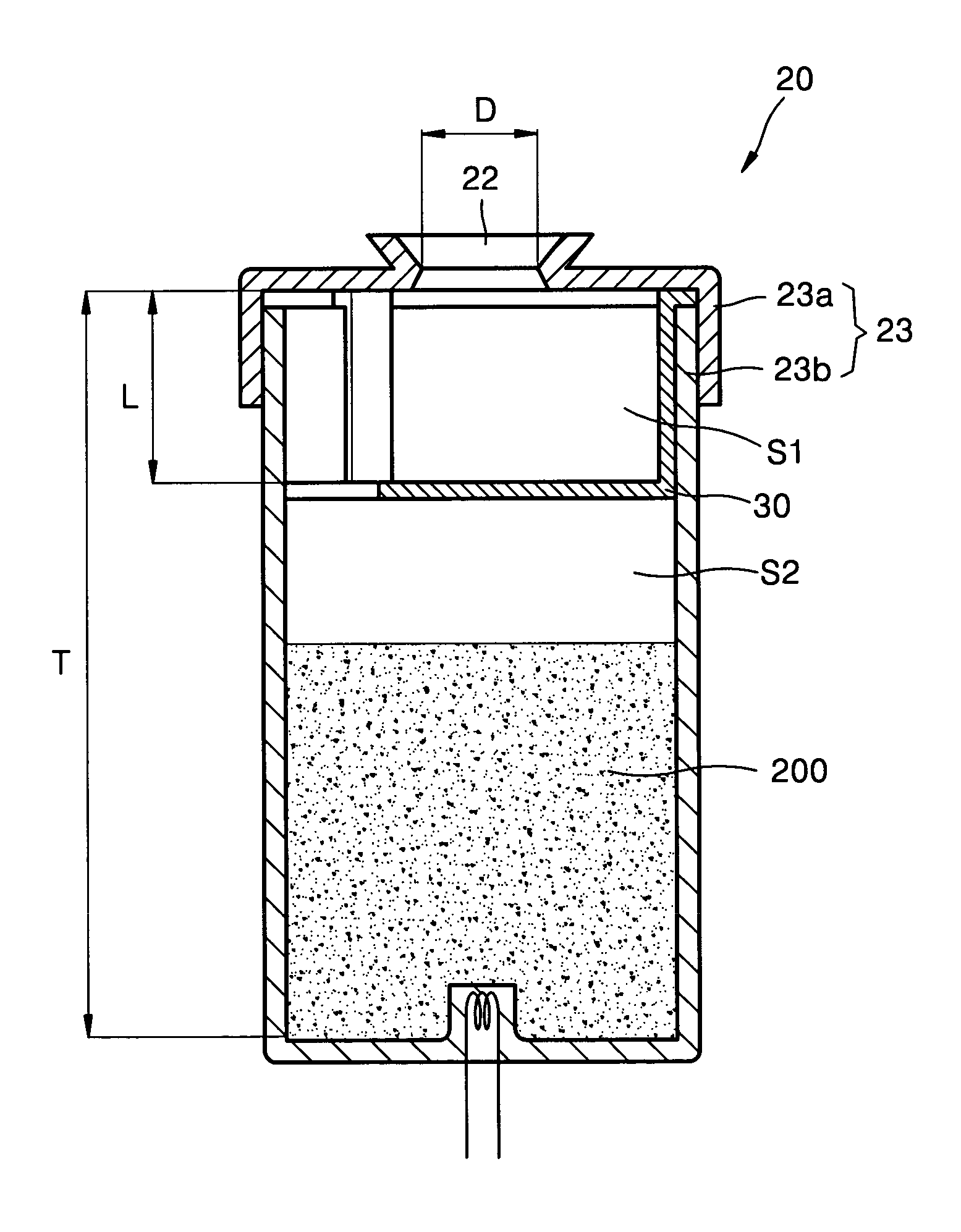
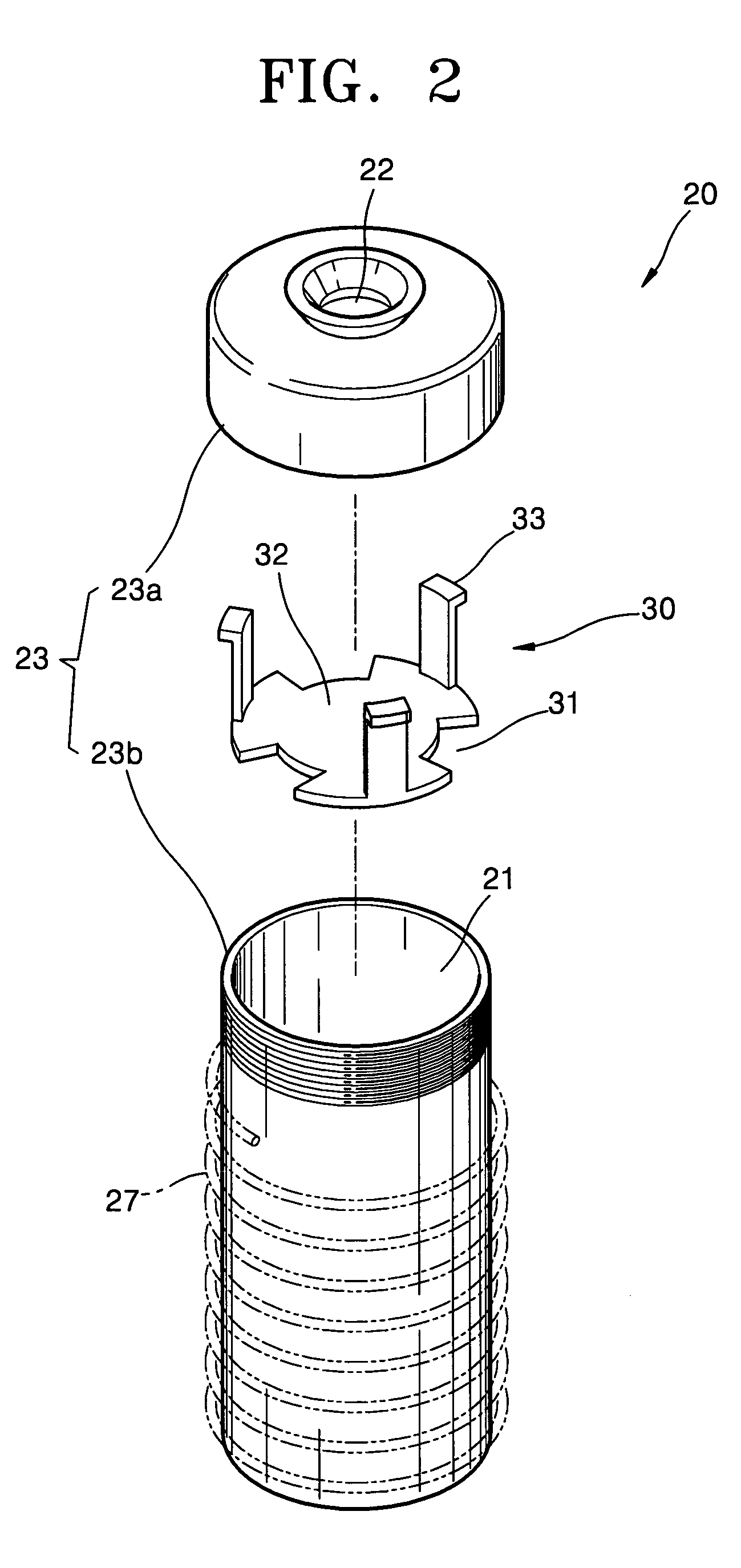
A deposition apparatus includes a vacuum chamber and a heating crucible. A substrate, on which deposition films are formed, is installed in the vacuum chamber. The heating crucible is installed opposite to the substrate so as to vaporize an organic compound. The heating crucible includes a main body and an inner plate. The main body includes a space which contains the organic compound and a nozzle through which the organic compound that is vaporized is discharged. The inner plate is installed within the main body and includes at least one opening formed around an edge of an area facing the nozzle, so as to transmit the vaporized organic compound.

Description

[0001] This application claims the benefit of Korean Patent Application No. 2002-43272, filed Jul. 23, 2002 in the Korean Intellectual Property Office, the disclosure of which is incorporated herein by reference.[0002] 1. Field of the Invention[0003] The present invention relates to a heating crucible and a vacuum deposition apparatus using the same, and more particularly, to a vacuum deposition apparatus using an improved heating crucible that prevents scattering of a vaporable material.[0004] 2. Description of the Related Art[0005] An electroluminescent (EL) device, which is a spontaneous emission display panel, is attracting attention as a next-generation display panel. An EL device provides a wide viewing angle, an excellent contrast, and a fast response characteristic. EL devices are classified into an inorganic EL device and an organic EL device according to a material that forms an emitting layer thereof. An organic EL device provides high brightness, excellent driving voltag...

Claims


Application Information

Patent Timeline
IPC IPC(8): H05B33/10C23C14/12C23C14/24H01L51/50
CPCC23C14/12C23C14/243C23C14/24H05B33/10
Inventor KEUM, JI HWANJI, CHANG SOONKIM, HYUNG MINNAMGOONG, SUNG TAE
Owner SAMSUNG DISPLAY CO LTD
Learn More