Vapor deposition crucible, thin-film forming apparatus comprising the same, and method of producing display device

Inactive Publication Date: 2007-08-02
HITACHI DISPLAYS
View PDF11 Cites 52 Cited by
  • Summary
  • Abstract
  • Description
  • Claims
  • Application Information

AI Technical Summary

Benefits of technology

[0067] In the present invention, the vapor of the material (the organic material) which evaporates from the opening portion of the orifice plate defining the crucible main body (evaporation chamber) to the exterior of the crucible main body is less likely to be cooled after the completion of the vapor deposition since the orifice plate is covered by the cap portion which directly receive the heat from the heater. This prevents solidification of the material that has evaporated from the crucible main body on the surface of the cap portion opposing the crucible main body, or solidification of the material in the interior of the opening portion which functions as the orifice. Accordingly, separation of the crucible main body and the cap portion is readily realized, and introduction of the material into the crucible main body is facilitated.
[0068] In addition, deposition of the evaporated material near the orifice plate (on the upper side of the upper surface of the orifice in the crucible) is prevented, and attachment of the peeled deposited material to the opening of the orifice is also prevented, and therefore, the rate of the vapor deposition is stabilized.
[0069] When the gap between the side surface of the orifice plate and the inner wall of the crucible main body is used for the orifice hole, the temperature of the orifice hole increases to an even higher temperature when the heater is energized and deposition of the material near the orifice hole will be prevented.
[0070] By constituting the cap portion to have a structure capable of directly receiving the heat from the heater, the opening portion (discharge aperture) of the cap portion can be designed to have a smaller diameter and a larger hole length since the c

Problems solved by technology

This will result in the difficulty of separating the crucible main body 31 and the cap portion 32, or even if separated, tremendous extra effort for such separation, a

Method used


Image

  • Vapor deposition crucible, thin-film forming apparatus comprising the same, and method of producing display device
  • Vapor deposition crucible, thin-film forming apparatus comprising the same, and method of producing display device
  • Vapor deposition crucible, thin-film forming apparatus comprising the same, and method of producing display device

Examples


example 1

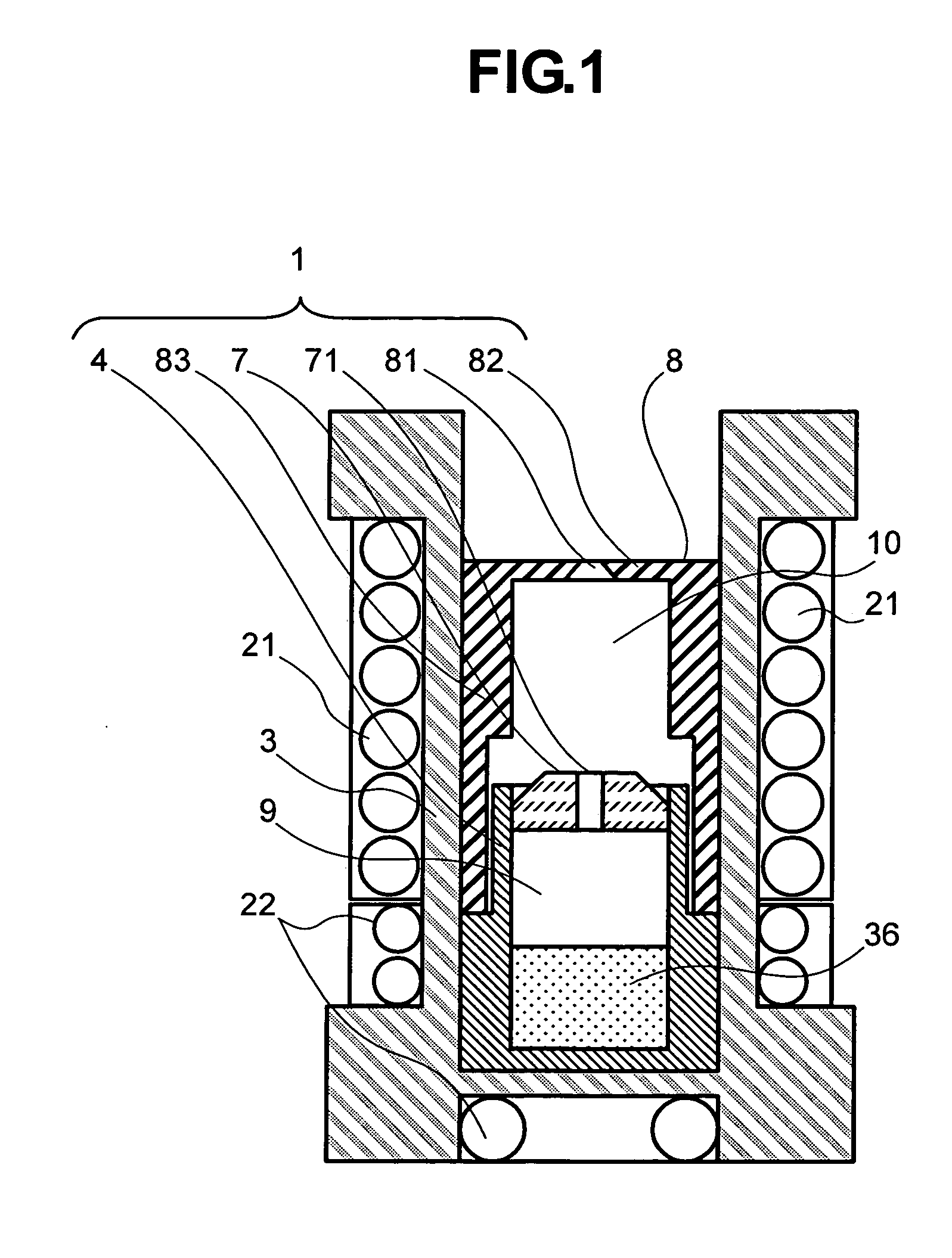
[0089]FIG. 1 is a cross sectional view showing the constitution of the crucible according to the present invention. The vapor deposition crucible 1 is inserted in a cylindrical heater case 3 provided with an upper heater 21 and a lower heater 22 for heating. The upper and the lower heaters 21 and 22 are sheath-type heaters which can be controlled independently from each other.

[0090] One end of the longitudinal axis of the cylindrical heater case 3 is formed with a bottom surface, and the other end of the heater case 3 is open in contrast to the bottom end. In the following description, the constitution of the vapor deposition crucible 1 is described by referring the end of the heater case 3 as the “lower” and the other end as the “upper”. The vapor deposition crucible 1 has a crucible main body 4 which is provided in the heater case 3 on the lower side, and the bottom of the crucible main body 4 is supported by the bottom of the heater case 3. A space 1e defined in the interior of ...

example 2

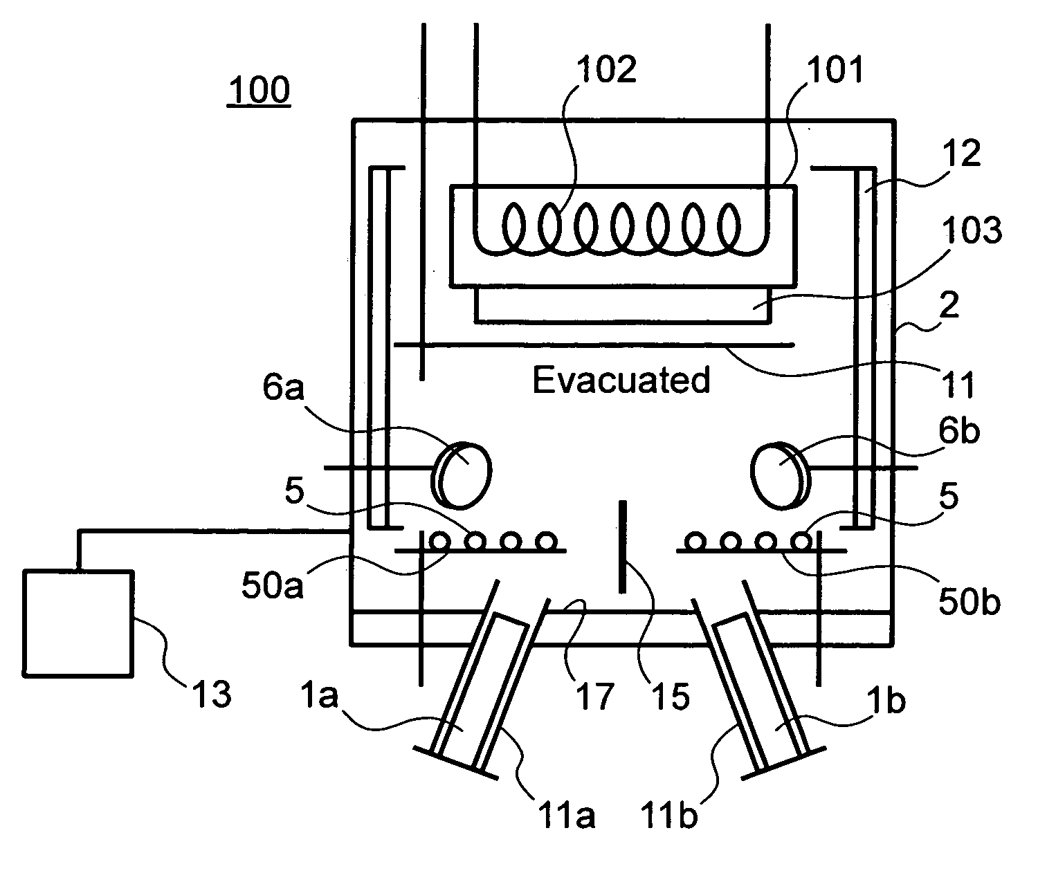
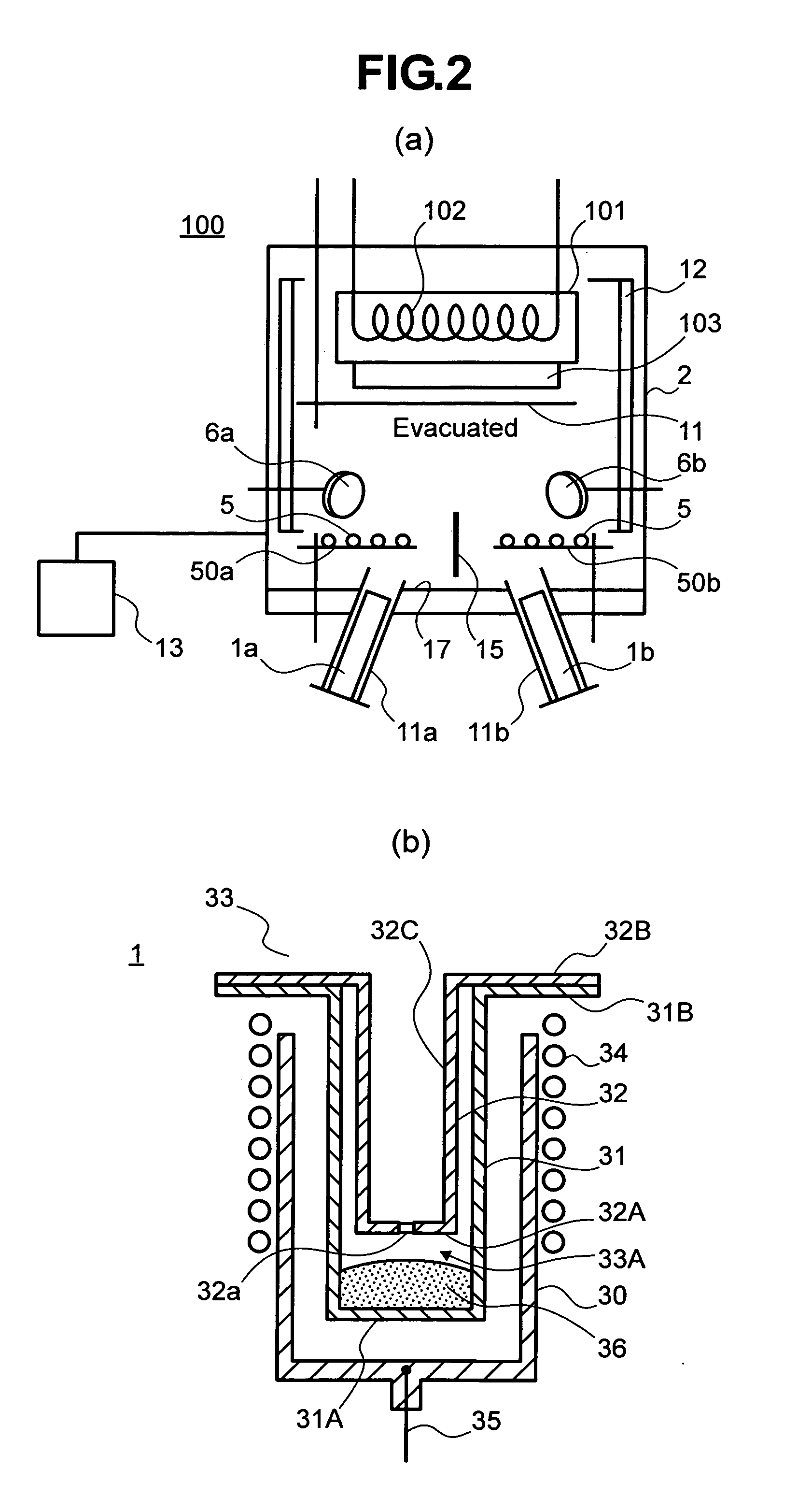
[0115] In this Example, a crucible structure adapted for use in the production of a display device (for example, organic EL panel) by mask vapor deposition is described. The inventors of the present invention investigated application of the present invention to the mask vapor deposition in which the vapor deposition layer is formed in a particular patterned region of the substrate 103. FIG. 12 shows the basic constitution (concept) of the mask vapor deposition. The formation of the vapor deposition layer on the main surface of the substrate 103 by the mask vapor deposition is carried out by bringing a vapor deposition mask 161 having a pattern of holes 164 corresponding to the pixels arranged in the main surface in close contact with the main surface of the substrate 103. The main surface of the substrate 103 before the mask vapor deposition is formed with the plurality of pixels, for example, defined by the insulating partition walls (banks) 128 described in relation to Example 1, ...

example 3

[0126] This Example shows another embodiment for the orifice plate 7 and its opening portion 71 of the crucible 1 described in Examples 1 and 2. The orifice plate 7 shown in FIGS. 1, 3, 11, 13, and 14 is formed with an opening portion 71 extending in vertical direction of the crucible 1.

[0127] In this Example, the opening portion 71 of the orifice plate 7 is not formed in the orifice plate 7 but the opening portion 71 is formed as a gap between the orifice plate 7 and the inner wall of the crucible main body 4 (the part where the orifice plate 7 is supported). The orifice plate 7 shown in FIG. 15 is a block member having no opening formed therethrough. While this orifice plate 7 is depicted as if it was floating in the upper portion of the crucible main body 4, it is actually supported by at least 1 support member, and preferably, by several support members (not shown) to the crucible main body 4. In other words, the opening portion 71 is formed as a region defined by the outer wal...


PUM

PropertyMeasurementUnit
Temperatureaaaaaaaaaa
Pressureaaaaaaaaaa
Distanceaaaaaaaaaa

Abstract

For lasting stable vapor deposition of a material for a long term, the present invention provides the vapor deposition crucible comprising an evaporation chamber defined by a container part of the material and an orifice plate controlling vapor pressure of the material evaporated therein, and a pressure-controlling chamber defined in a space between the orifice plate and a discharge plate through which the material is discharged to the exterior of the vapor deposition crucible. A protrusion extending outwardly from the pressure-controlling chamber and having a second opening on its distal end may be provided on the upper surface of the discharge plate, and a heater may be provided on the side surface of the protrusion to oppose the side surface of the protrusion with an insulation mechanism provided at a position higher than the heater but lower than the second opening. In the vapor deposition crucible, temperature of the pressure-controlling chamber may be kept higher than that of the evaporation chamber by the other heaters.

Description

[0001] The present application claims priority from Japanese application JP 2005-359781 filed on Dec. 14, 2005, the content of which is hereby incorporated by reference into this application. BACKGROUND OF THE INVENTION [0002] 1. Field of the Invention [0003] This invention relates to a production of an electronic device such as a display device comprising the step of vapor depositing an organic material, a vapor deposition crucible adapted for use in such production, and a thin film forming apparatus (organic thin film forming apparatus) using such a crucible. [0004] 2. Description of the Related Art [0005] Various methods have been proposed for use in forming a thin film from an organic material. However, there are various process constraints unique to the organic material, and some materials had difficulty in the use for a stable vapor deposition. Recently, the so called organic EL panel which displays an image by a panel produced by the vapor deposition technology of such an org...

Claims


Application Information

Patent Timeline
IPC IPC(8): B05D5/06C23C16/00
CPCC23C14/243H01L51/56H01L51/001H10K71/164H10K71/00
Inventor TAKANOSU, KEIJIMATSUURA, HIROYASU
Owner HITACHI DISPLAYS
Why Eureka
Try Eureka