
Powder additive for powder metallurgy, iron-based powder mixture for powder metallurgy, and method for manufacturing the same

a technology of powder metallurgy and additives, which is applied in the direction of metal-working apparatuses, transportation and packaging, thin material processing, etc., can solve the problems of increased useless binder floating free, decreased green density, and insufficient improvement of segregation of iron-based powder mixtures. , to achieve the effect of low cost and effective manufacturing and reduced segregation

Inactive Publication Date: 2004-02-26
JFE STEEL CORP
View PDF7 Cites 18 Cited by
  • Summary
  • Abstract
  • Description
  • Claims
  • Application Information

AI Technical Summary

Benefits of technology

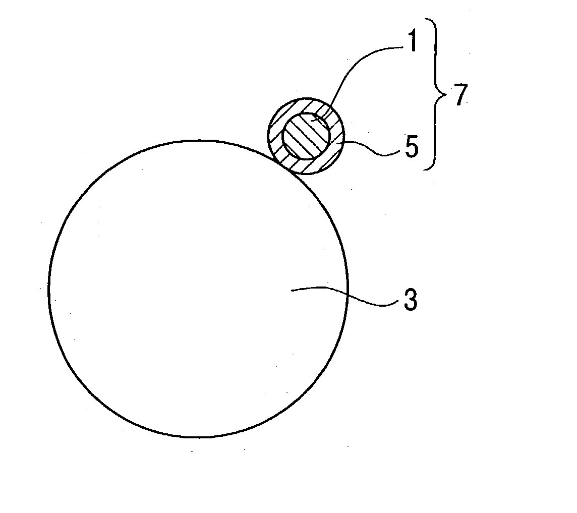
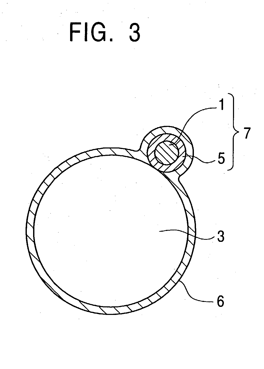
The invention provides an iron-based powder mixture for powder metallurgy that has reduced segregation and improved green density without decreasing the effectiveness of the powder additive. This is achieved by using a powder additive that includes a body and an organic binder provided to the surface of the powder additive particles. The powder additive can be a coating of organic binder on the surface of the powder additive particles or a processing liquid containing the organic binder. The invention also provides a method for manufacturing the iron-based powder mixture by heating and cooling the mixture. The resulting powder mixture has improved properties for powder metallurgy applications.

Problems solved by technology

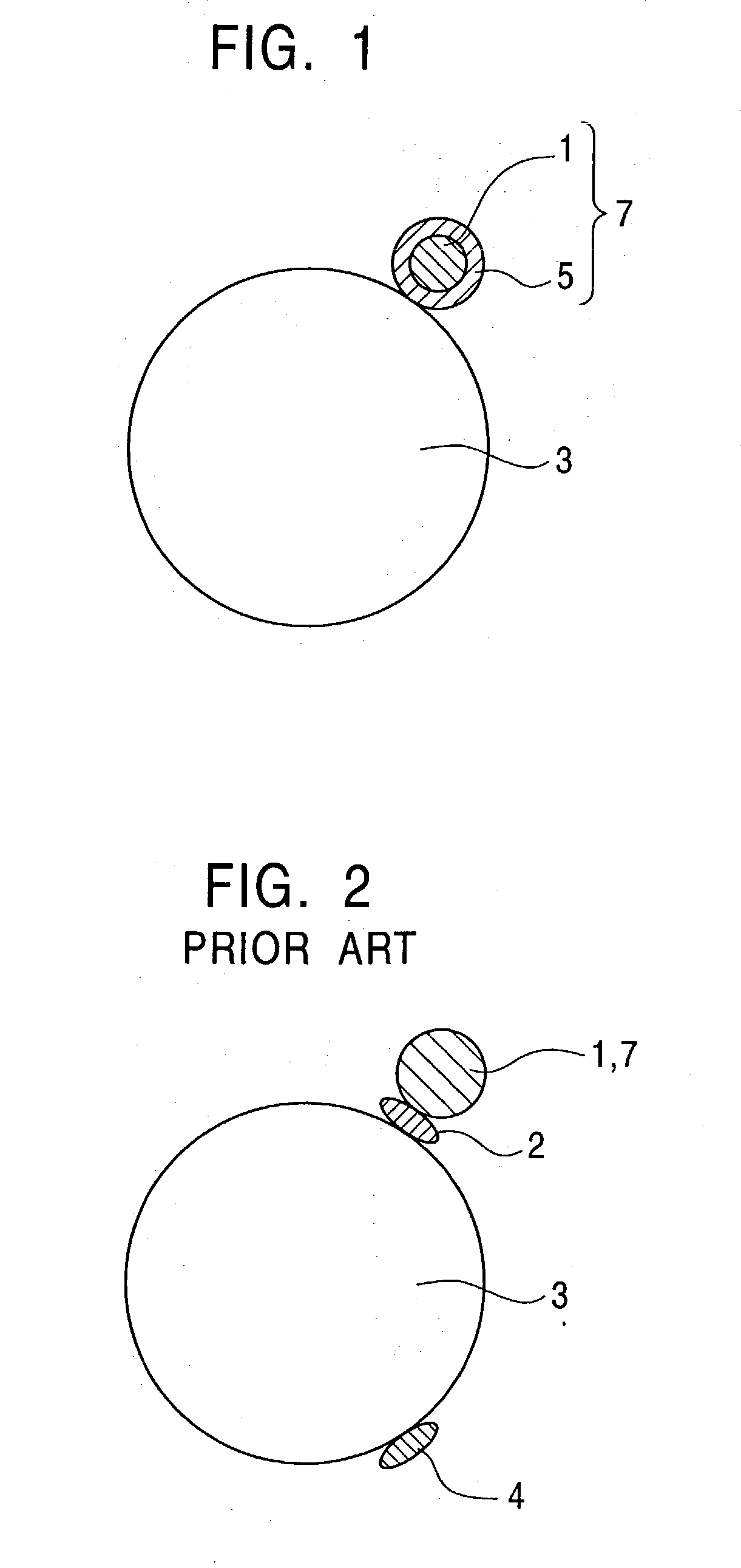
However, with either method, increasing the amount of organic binder added to sufficiently prevent segregation inevitably leads to an increase in useless binder 4 which does not contribute to binding of the iron-based powder and the powder additives, but simply adheres to the surface of the powder additive or the iron-based powder, causing problems such as a decrease in green density because useless binder occupies volume that inhibits the iron base powder.
Also, there is an increase in useless binder floating free, which does not adhere to the raw material powders.
Accordingly, the above methods do not sufficiently improve segregation of iron-based powder mixture for powder metallurgy.

Method used


Image

  • Powder additive for powder metallurgy, iron-based powder mixture for powder metallurgy, and method for manufacturing the same
  • Powder additive for powder metallurgy, iron-based powder mixture for powder metallurgy, and method for manufacturing the same
  • Powder additive for powder metallurgy, iron-based powder mixture for powder metallurgy, and method for manufacturing the same

Examples


second example

[0138] Atomized pure iron powder (KIP (TM) 301A: a product by JFE Steel Corp.), reduced iron powder (KIP (TM) 255M), 4% Ni by mass--1.5% Cu by mass--0.5% Mo by mass partially alloyed steel powder (KIP (TM) SIGMALOY 415S), 2% Ni by mass--1% Mo by mass partially alloyed steel powder (KIP (TM) SIGMALOY 2010), and 3% Cr by mass--0.3% V by mass completely alloyed steel powder (KIP (TM) 30CRV), were prepared as iron-based powder. Also, the graphite powder according to Invention examples S1 through S5 and Comparative examples S1 through S5 in the first Example were prepared as powder additives. The iron-based powder and the powder additive were mixed in a Henschel mixer at a predetermined temperature, thereby making an iron-based mixed powder for powder metallurgy. The types of iron-based powder used and the types of graphite powder, the amounts added, and the heat mixing temperature, are as shown in Table 6.

[0139] Note that the Ni, Cu, and Mo within the KIP (TM) SIGMALOY 415S were each ad...

third example

[0146] Atomized pure iron powder (KIP (TM) 301A and KIP 304A), reduced iron powder (KIP (TM) 255M), 4% Ni by mass--1.5% Cu by mass--0.5% Mo by mass partially alloyed steel powder (KIP (TM) SIGMALOY 415S), 2% Ni by mass--1% Mo by mass partially alloyed steel powder (KIP (TM) SIGMALOY 2010), and 3% Cr by mass--0.3% V by mass completely alloyed steel powder (KIP (TM) 30CRV), were prepared as iron-based powder. Also, the graphite powder according to Invention examples S1 through S4 and S2b and Comparative examples S1 through S4 in the first Example; the copper powders according to Invention examples S6, S7, and S9, and Comparative examples S6, S7, and S9, in the first Example; the Ni powder according to Invention example S11 and Comparative example S11 in the first Example; and the Mo--Fe powder according to Invention example S16 and Comparative example S16 in the first Example; were prepared as powder additives.

[0147] The iron-based powder, graphite powder which is a powder additive, a...

fourth example

[0161] An iron-based mixed powder for powder metallurgy was made in the same way as with the third Example, except that the primary mixing lubricant and the secondary mixing lubricant shown in Table 7 were not used.

[0162] Next, after adding a free lubricant shown in Table 9 in various ranges, the powder was mixed with powder mixers of various types as shown in Table 10, thus preparing various types of iron-based mixed powder for powder metallurgy.

[0163] Table 10 also shows the results of checking the flowability, ejection pressure, and green density of the iron-based mixed powder for powder metallurgy thus obtained.

[0164] The properties were evaluated as follows.

[0165] (1) Percentage of Secondary Particles Following Mixing

[0166] The lubricant is observed in a scanning electron microscope (SEM) reflection electron image as low-contrast particles corresponding to light element components. Accordingly, the image was analyzed for only the low-contrast particles, and the percentage by vo...


PUM

PropertyMeasurementUnit
particle sizeaaaaaaaaaa

Abstract

The surface of the body of powder additive for use in powder metallurgy is coated with an organic binder, thereby obtaining powder additive to cause adhesion of the powder additive to the surface of iron-based powder by the organic binder, thereby providing a powder additive with no segregation of components and excellent flowability and compression, and an iron-based powder mixture manufactured by mixing the powder additive and the iron-based powder.

Description

[0001] 1. Field of the Invention[0002] This invention relates to a powder additive for powder metallurgy, to be mixed in an iron-based powder which is a primary raw material powder to obtain a powder mixture for powder metallurgy, such as alloying powder or machinability improving powder or the like. Also, this invention relates to a method for manufacturing the powder additive for powder metallurgy. Further, this invention relates to an iron-based powder mixture for powder metallurgy wherein the powder additives for powder metallurgy are bonded to the surface of iron powder by an organic binder, and a method of producing thereof.[0003] 2. Description of the Related Art[0004] An iron-based powder mixture for powder metallurgy generally is an iron-based powder of iron powder or alloy steel powder or the like, to which powder additives for powder metallurgy and a lubricant are added as needed. Examples of the powder additives for powder metallurgy added include alloying powders such a...

Claims


Application Information

Patent Timeline
Patent Type & Authority Applications(United States)
IPC IPC(8): B22F1/00B22F1/10B22F1/102B22F1/148B22F3/02C22C33/02
CPCB22F1/0059Y10T428/2998B22F1/0077B22F1/0096B22F2003/023B22F2998/00B22F2999/00C22C33/0207B22F1/0062Y10T428/12181Y10T428/12049B22F1/02B22F1/108B22F1/102B22F1/148B22F1/10B22F1/00
Inventor OZAKI, YUKIKOUNAMI, SHIGERUUENOSONO, SATOSHI
Owner JFE STEEL CORP
Learn More