Beating arrangement

a technology of arrangement and cutting body, applied in the field of cutting body, can solve the problems of affecting the quality of the cutting body,

Inactive Publication Date: 2004-03-25
WERNER DOPPSTADT UMWELTTECHN
View PDF10 Cites 14 Cited by
  • Summary
  • Abstract
  • Description
  • Claims
  • Application Information

AI Technical Summary

Problems solved by technology

Due to the complex shape of the described flail mallet assembly its production is difficult and expensive.
With both arrangemen

Method used


Image

  • Beating arrangement
  • Beating arrangement
  • Beating arrangement

Examples


Embodiment Construction

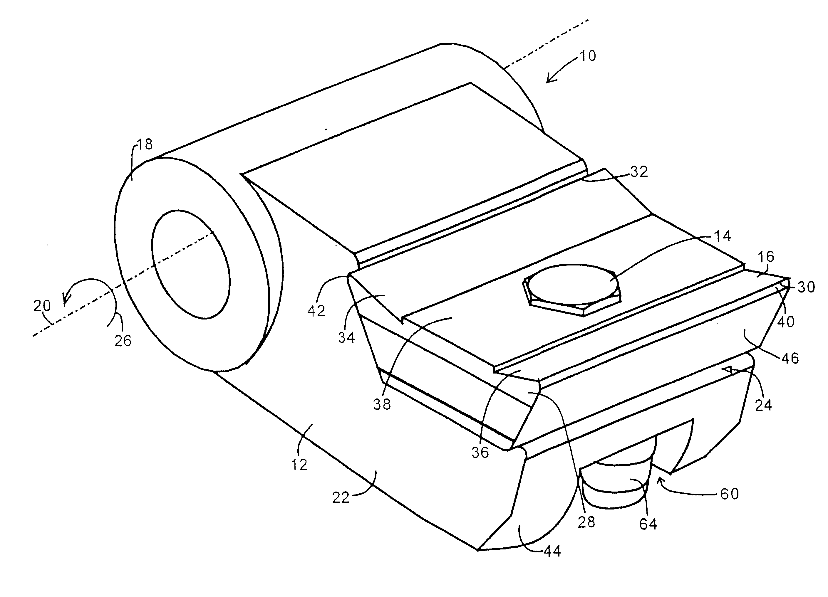
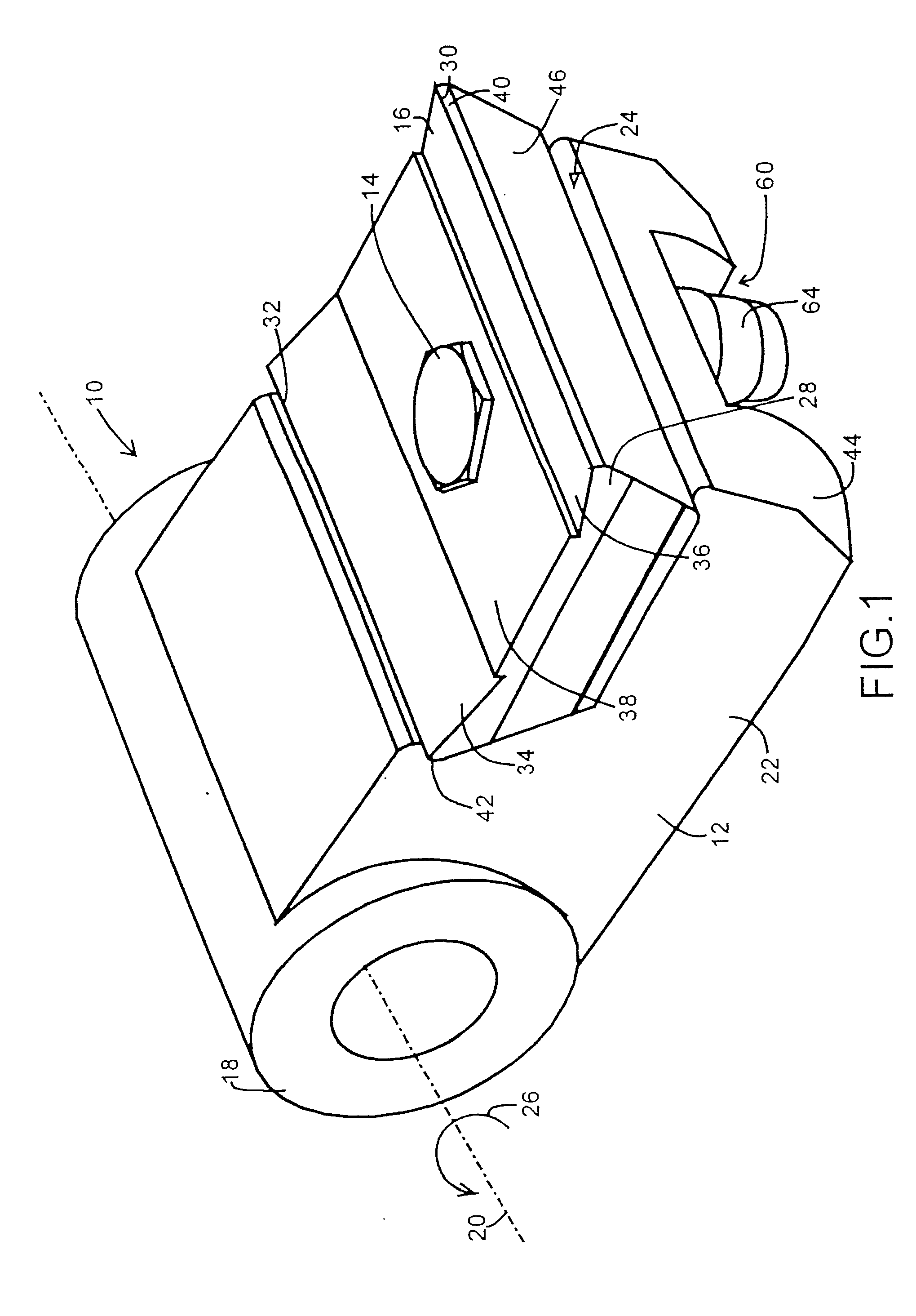
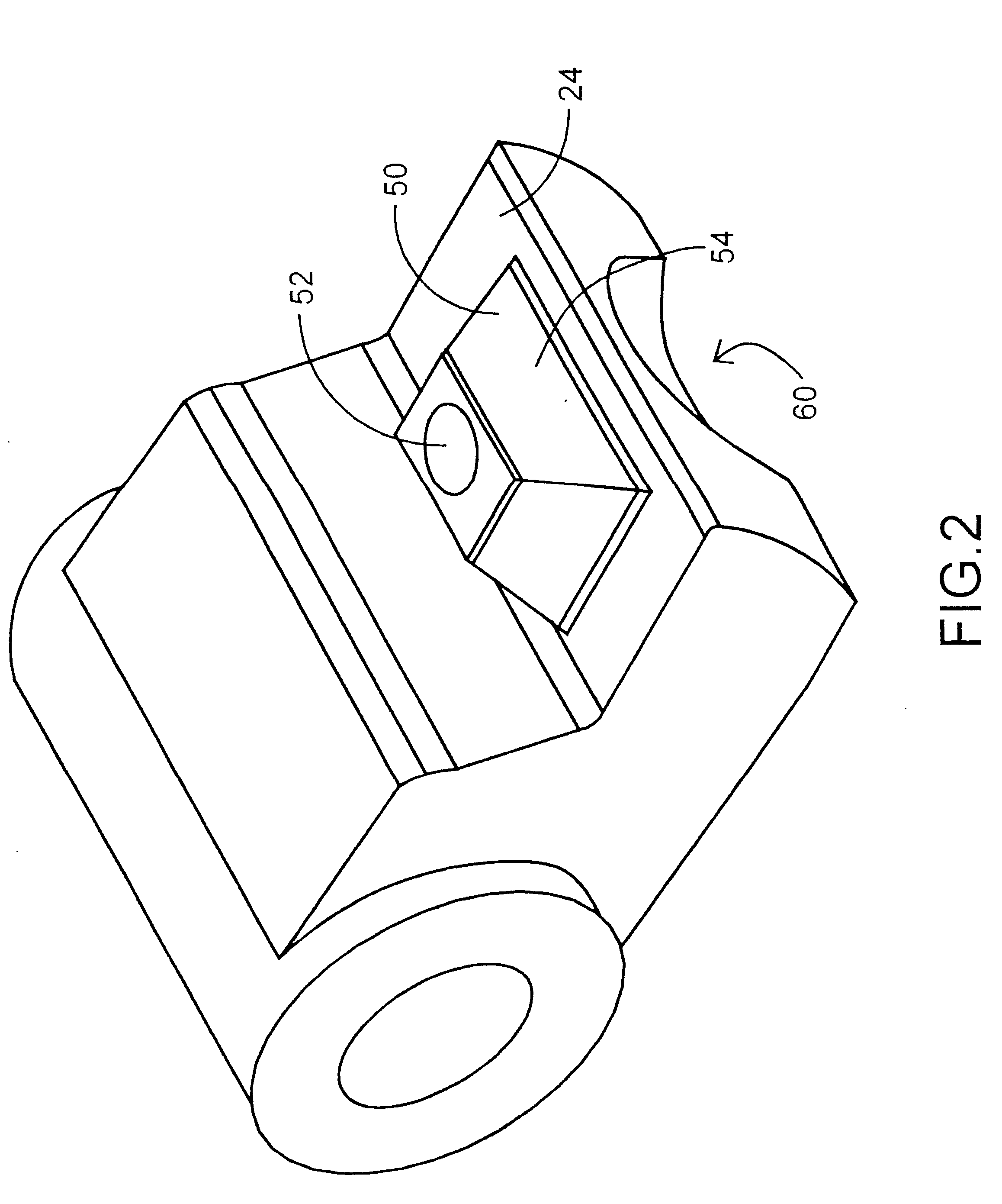
[0018] In FIG. 1, 10 denotes a rotor flail mallet. The rotor flail mallet 10 comprises a base body 12 and a cutting body 16 screwed onto it with a screw 14, which forms the tip of the flail mallet. The base body 12 consists of a hollow cylinder 18 being rotatably mounted about an axis 20. A projection 22 is provided at the hollow cylinder. The projection 22 is shaped essentially with a step, wherein the "step" has a surface 24 on which the cutting body 16 lies. The surface 24 is directed in the direction of the rotational movement represented by an arrow 26 in FIG. 1. It, therefore, forms the front surface of the base body 12. The cutting body 16 lies in a fitted manner on the base body 12. Due to the step-like arrangement the cutting body 16 is surrounded on two sides by the base body 12 and forms a unit therewith, where cutting material cannot enter into.

[0019] The cutting body 16 has a uniform trapezoid cross section over its entire width. The smaller parallel surface 26 of the t...


PUM


Abstract

The invention relates to a beating arrangement for a rotary shredder, comprising a base body (12) which is rotationally arranged around an axis (20) and a cutting body (16) which is detachably fixed onto a protruding part (22) of the base body. A protruding profile (50) is formed on the front surface thereof in the direction of rotation whereon the cutting body (16) forms a positive fit. The profile (50) can be embodied in the form of a protruding truncated pyramid, whose base surface lies on the plane of cutting edges (30, 32) which are bilaterally symmetrical in relation to a surface which extends tangentially in relation to a circumference of rotation. The cutting body can be fixed by means of a screw (14), which extends through the centre of the cutting body and the profile.

Description

[0001] Applicants claim priority under 35 U.S.C. .sctn.119 of GERMAN Application No. 101 01 434.1 filed on Jan. 13, 2001. Applicants also claim priority under 35 U.S.C. .sctn.365 of PCT / EP02 / 00100 filed on Jan. 8, 2002. The international application under PCT article 21(2) was not published in English.[0002] The invention relates to a flail mallet assembly for rotor shredders with a base body rotatably mounted about an axis and a cutting body releaseably fixed to a projection of the base body. Such flail mallets are used as striking tools for rotor shredders for, for example, plastic, wood or the like.STATE OF THE ART[0003] From the DE 35 45 708 C2 a flail mallet assembly is known, wherein a cutting body shaped as a tooth is releaseably fixed with its shaft in a recess. The fixing is carried out by means of a screw extending through a bore hole in the base body and the shaft of the cutting body. The shaft is provided with a projecting edge at its end extending around a projection in...

Claims


Application Information

Patent Timeline
IPC IPC(8): B02C13/28B02C18/18
CPCB02C18/18B02C13/28
Inventor DOPPSTADT, WERNER
Owner WERNER DOPPSTADT UMWELTTECHN
Why Eureka
Try Eureka