Method and apparatus for alignment of anti-scatter grids for computed tomography detector arrays

Inactive Publication Date: 2004-03-25
KONINKLIJKE PHILIPS ELECTRONICS NV
View PDF8 Cites 32 Cited by
  • Summary
  • Abstract
  • Description
  • Claims
  • Application Information

AI Technical Summary

Benefits of technology

0014] One advantage of the present invention resides in a substantial reduction in stack-up errors in the alignment of the anti-scatter elements.
0015] Another advantage of the present invention resides in improved accuracy in alignment of anti-scatter plates or elements.
0016] Another advantage of the present invention resides in an improved method for manufacturing highly precise and accurate alignment plates for radiation detectors which is

Problems solved by technology

Shadowing, in turn, leads to reduced x-ray intensities and image artifacts which generally manifest as rings in the image reconstruction.
Spatially non-uniform shadowing also leads to spectral differences in the detected x-rays and non-linear detector array characteristics.
Furthermore, if the anti-scatter plates are inadequately secured, mechanical vibrations can produce temporally varying shadowing due to mechanical flexing of the tall, thin anti-scatter plates during gantry rotation which leads to a variety of image artifacts.
A common problem in such detec

Method used


Image

  • Method and apparatus for alignment of anti-scatter grids for computed tomography detector arrays
  • Method and apparatus for alignment of anti-scatter grids for computed tomography detector arrays
  • Method and apparatus for alignment of anti-scatter grids for computed tomography detector arrays

Examples


Embodiment Construction

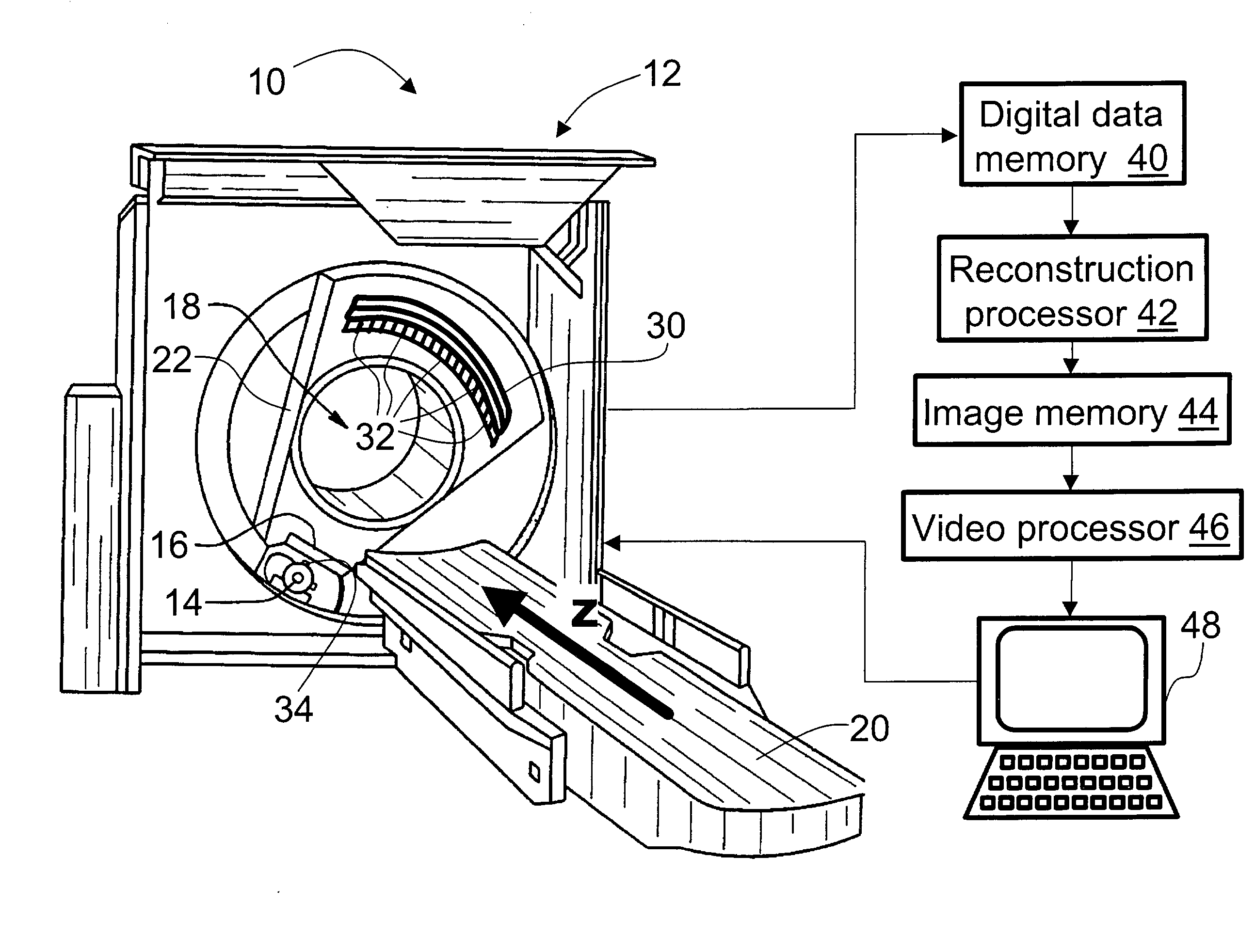
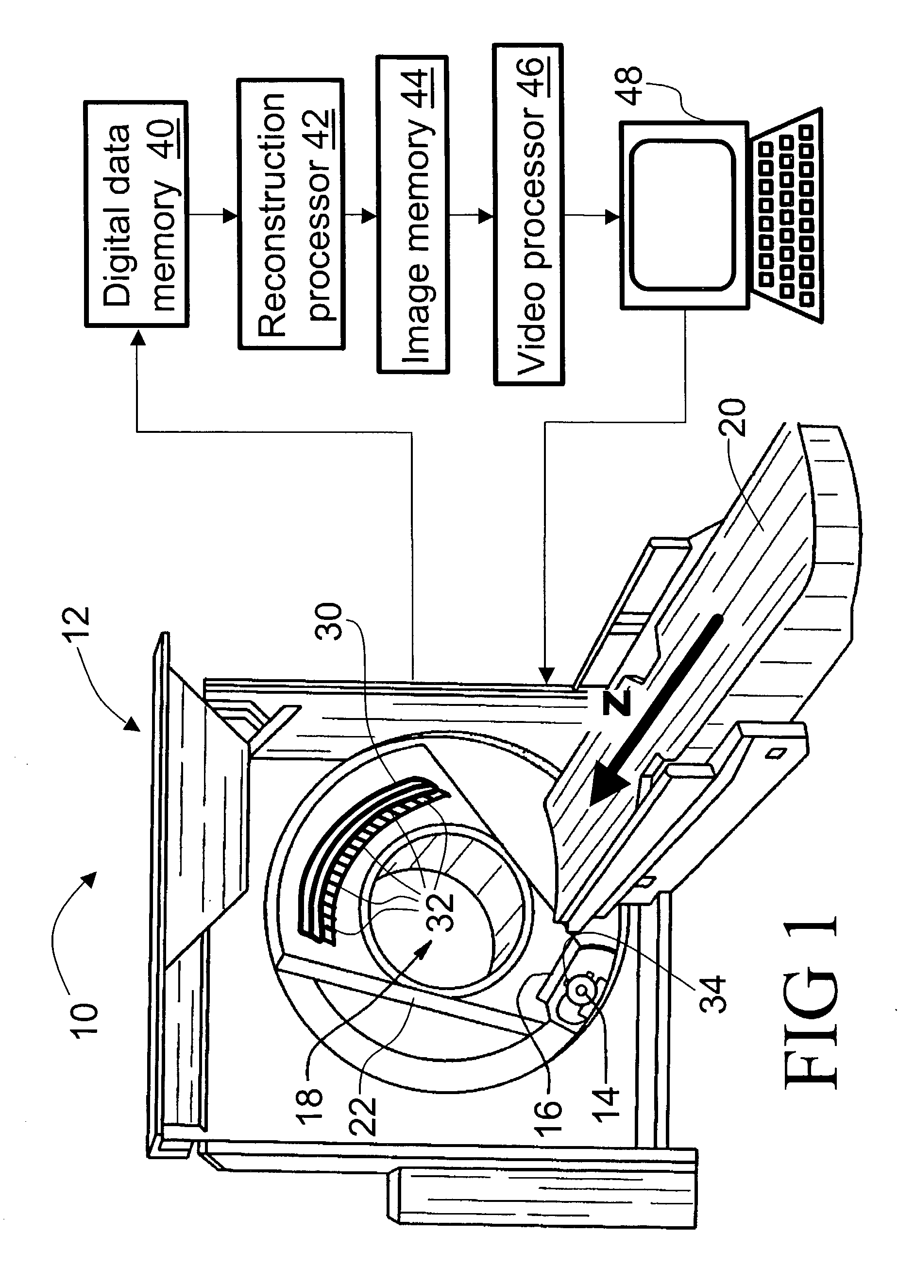
[0036] With reference to FIG. 1, a computed tomography (CT) imaging apparatus or CT scanner 10 includes a gantry 12. An x-ray source 14 and a source collimator 16 cooperate to produce a fan-shaped, cone-shaped, wedge-shaped, or otherwise-shaped x-ray beam directed into an examination region 18 which contains a subject (not shown) such as a patient arranged on a subject support 20. The subject support 20 is linearly movable in a Z-direction while the x-ray source 14 on a rotating gantry 22 rotates around the Z-axis.

[0037] In an exemplary helical imaging mode, the rotating gantry 22 rotates simultaneously with linear advancement of the subject support 20 to produce a generally helical trajectory of the x-ray source 14 and collimator 16 about the examination region 18. However, other imaging modes can also be employed, such as a single- or multi-slice imaging mode in which the gantry 22 rotates as the subject support 20 remains stationary to produce a generally circular trajectory of t...


PUM


Abstract

A radiation detector (30) for a computed tomography scanner (12) includes a support structure (62). An alignment board (60) secures to the support structure (62) and includes photolithographically defined alignment openings (70) arranged to define a spatial focal point (34) relative to the alignment board (60). An anti-scatter element (32) is disposed on the support element (62) and includes one or more protrusions (86) which mate with the alignment openings (70) of the alignment board (60) to align the anti-scatter element (32) with the spatial focal point (34). A detector board (104) includes alignment structures (106) that align the detector board (104) with the anti-scatter element (32).

Description

BACKGROUND OF THE INVENTION[0001] The present invention relates to the diagnostic imaging arts. It particularly relates to computed tomography imaging employing an x-ray source and a two-dimensional detector array that enables rapid acquisition of volumetric x-ray absorption imaging data, and will be described with particular reference thereto. However, the invention will also find application in other types of radiation detectors for a variety of imaging applications employing x-rays, visible light, radiation from an administered radiopharmaceutical, or other types of radiation. The invention will further find application in non-imaging radiation detectors.[0002] Computed tomography (CT) imaging typically employs an x-ray source that generates a fan-beam, wedge-beam, or cone-beam of x-rays that traverse an examination region. A subject arranged in the examination region interacts with and absorbs a portion of the traversing x-rays. A one- or two-dimensional radiation detector inclu...

Claims


Application Information

Patent Timeline
IPC IPC(8): G21K1/02
CPCA61B6/4258G21K1/025
Inventor LUHTA, RANDALL P.BRUNNETT, WILLIAM C.MATTSON, RODNEY A.
Owner KONINKLIJKE PHILIPS ELECTRONICS NV
Why Eureka
Try Eureka