Variable mirror and information apparatus comprising variable mirror

a technology of variable mirrors and information apparatuses, which is applied in the direction of instruments, lenses, record information storage, etc., can solve the problems of difficult to achieve at the same time a broad enough range of wave front correction and adequate responsiveness and accuracy, and difficult to accurately detect such a broad variety of wave front aberration types

Inactive Publication Date: 2004-04-01
PANASONIC CORP
View PDF7 Cites 41 Cited by
  • Summary
  • Abstract
  • Description
  • Claims
  • Application Information

AI Technical Summary

Benefits of technology

0047] An information device according to the invention is an information device for irradiating a medium with forward light emitted from a light source and detecting information stored by the medium on the basis of backward light modulated by the medium, and comprises a wave front detector for detecting the wave fronts of the backward light in respect of each of a plurality of detection regions included in a section across the optical axis of the backward light; a wave front corrector, provided within the optical path of the forward light and / or backward light, for locally varying the optical path length of the forward light and / or backward light by an action of a plurality of drive units arrayed on a plane crossing the optical path; and a control unit for supplying a plurality of drive signals to the wave front corrector on the basis of a plurality of outputs of the wave front detector and reconstructing the whole wave fronts of the backward light wherein the wave front corrector comprises a deformable mirror according to any of the foregoing paragraphs.
0048] In a certain preferable embodiment of the present invention, the control unit comprises a steady deviation compensation unit having an integrator for integrating the outputs of the wave front detector and an undiagonal first matrix computing unit for linearly converging the outputs of the integrator, a stabilizing compensation unit having an undiagonal second matrix computing unit for computing and predicting the state of the wave front corrector from the output of the steady deviation compensation unit and the output of the wave front detector, and a diagonal converting unit, to which the output of the steady deviation compensation unit and the output of the stabilizing compensation unit are inputted, for generating drive signals for drive units.

Problems solved by technology

First, as the detection and correction of wave front aberrations are limited to a specific type or another, it is not possible all the time to address a wave front aberration of a desired type. For instance if the hologram 309 and the optical detector 307 are so designed as to permit detection of coma aberrations in the direction of the Y axis as shown in FIG. 26(b), no other wave front aberrations (such as coma aberrations in the direction of the X axis, spherical aberrations and astigmatisms) can be detected accurately. The same is true of the case shown in FIG. 26(c), wherein no others than spherical aberrations can be detected accurately. However, usual wave front aberrations arise from combinations of causes including a tilt, a variation in the thickness of the disk substrate, double refraction and smear with a fingerprint or the like, but the aberrations that arise are not always confined to any specific type.
Accurate detection of such a broad variety of wave front aberration types is difficult with a configuration for aberration detection based on a specific pattern of wave front aberration.
Similarly, in correcting wave front aberrations, the electrode pattern for drying liquid crystals for correcting coma aberrations and that for correcting spherical aberrations differ from each other, and accurate detection of a broad variety of wave front aberration types is difficult with a configuration for aberration detection based on a specific pattern of wave front aberration.
Second, it is difficult to achieve at the same time a broad enough range of wave front correction and adequate responsiveness and accuracy.
In the case of a wave front converting element using liquid crystals, it is possible to widen the range of wave front correction by thickening the liquid crystal layer, but this would invite a deterioration in correction accuracy due to a drop in transmission efficiency and response speed, and increased discontinuity of the optical path length between electrode patterns.
On the other hand, in a wave front converting element using a deformable mirror, as the only electrostatic force working on the deformable plate is an attracting force, there is a problem that in the configuration according to the prior art, active drive is only possible in the direction of bringing the deformable plate towards the electrode.
Therefore, the only driving force in the reverse direction is only a passive one deriving from the righting force of the deformable plate which has been once deformed, and this lack of symmetry of the driving forces results in poor control accuracy and responsiveness.
Moreover, bidirectional driving by utilizing such a passive force inevitably requires the use of a position deformed in advance to some extent as the reference face, it is made difficult to reproduce the shape of the reference face stably by fluctuations in drive sensitivity from one unit to another, and this invites a deterioration in the accuracy of correction.

Method used


Image

  • Variable mirror and information apparatus comprising variable mirror
  • Variable mirror and information apparatus comprising variable mirror
  • Variable mirror and information apparatus comprising variable mirror

Examples


embodiment 1

[0088] (Embodiment 1)

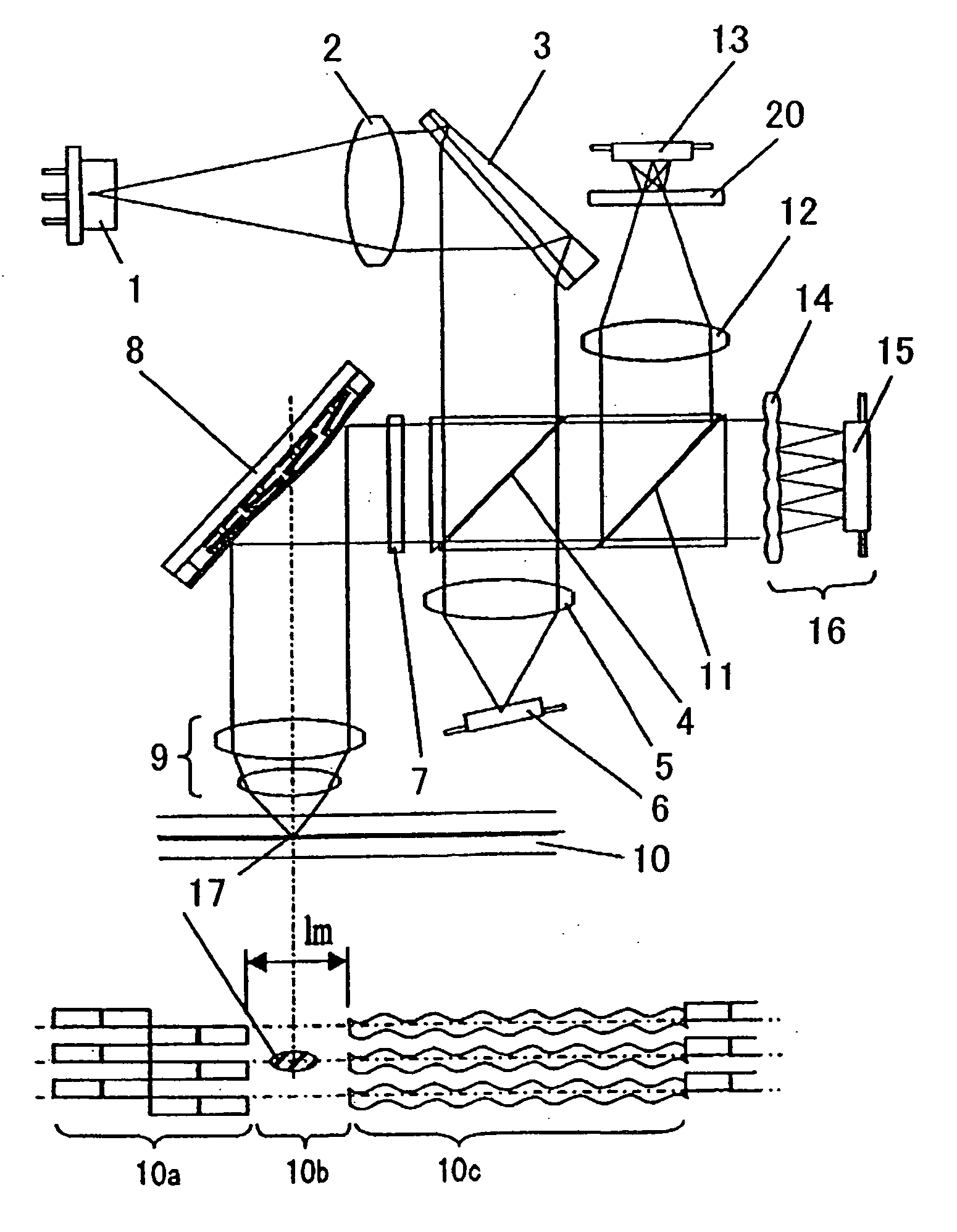
[0089] First, an information device according to a first embodiment of the present invention will be described with reference to FIG. 1. FIG. 1 is a schematic configurational diagram of this embodiment of the present invention. In the information device of FIG. 1, a GaN-based violaceous semiconductor laser 1 of 405 nm in laser wavelength, which serves as the light beam source, emits laser beams, which are to function as "write / read beams" for a recording medium. The beams emitted by the semiconductor laser 1, after being converted into substantially parallel beams by a collimating lens 2, are brought to incidence on a beam shaping prism 3. The beam shaping prism 3 is so configured by bonding together two glass members differing in refractive index as to reduce chromatic aberrations, and can shape oval beams into circular beams.

[0090] Light beams emitted from the beam shaping prism 3 are separated by a polarizing splitter 4 into P polarized beams and S-polarized ...

embodiment 2

[0213] (Embodiment 2)

[0214] Next, an information device according to a second embodiment of the present invention will be described with reference to FIG. 9. FIG. 9 shows a schematic configuration of this embodiment of the present invention.

[0215] The deformable mirror 8 according to this embodiment of the present invention has the same configuration as that described with reference to Embodiment 1.

[0216] The information device according to this embodiment of the present invention uses a plurality of light sources.

[0217] First will be described light emitted from a laser module 60 which integrates a photodetector and a GaN-based semiconductor laser of 405 nm in wavelength, which serves as a light source for a blue light recording disk.

[0218] Blue light beams emitted from the laser module 60 are converted into parallel beams by a collimator lens 61. A beam shaping prism 62 shape oval blue light beams into a circular shape. The shaped beams come incident on a polarization hologram 63....

embodiment 3

[0261] (Embodiment 3)

[0262] A deformable mirror according to another embodiment of the present invention will be described with reference to FIG. 13. FIG. 13. shows a schematic configuration of this embodiment of the present invention. Incidentally. in FIG. 13, common members with the first embodiment of the present invention are denoted by the same reference signs as their respective counterparts in FIG. 3.

[0263] The substrate 21 is formed of an Si material, whose thermal expansion coefficient is 2.8 trough 7.3.times.10.sup.-6. A reflective film 83 is formed by sputter-vapor deposition of a metallic material having a greater thermal expansion coefficient than the substrate 21. Where the material of the reflective film 83 is Al, its thermal expansion coefficient is about 23.6.times.10.sup.-6.

[0264] As the reflective film 83 is formed in a high temperature condition of about 450.degree. C. and moreover is coupled to the substrate 21 at its periphery 84, because of the difference in t...


PUM

PropertyMeasurementUnit
laser wavelengthaaaaaaaaaa
refractive indexaaaaaaaaaa
thicknessaaaaaaaaaa

Abstract

A deformable mirror according to the invention comprises a substrate, a reflector which is supported by said substrate and the shape of whose reflecting areas is variable, and a plurality of drive units for independently driving a plurality of regions of the reflector and thereby controlling the distances between said plurality of regions and said substrate. Each of the plurality of drive units comprises a plurality of electrodes disposed over said substrate, a tilt member which is rotated round the axis of tilt by being attracted by the selected one of the plurality of electrodes, and an action member for varying the distance between a specific region of the reflector and said substrate following the motion of the tilt member.

Description

DESCRIPTION[0001] The present invention relates to a deformable mirror comprising a displaceable light reflecting area, and an information device capable of reading information out of a storage medium and / or writing information onto a storage medium. The invention also relates to an optical compensation device and a wave front detection device for detecting and correcting the wave front of light beams coming incident from an external light source or of light beams from a light source provided inside.[0002] As an example of information device for optically detecting information according to the prior art, an optical disk device will be described. The optical disk device irradiates an optical disk, which is its recording medium, with forward light emitted from a laser beam source and detects variations in the intensity of the. reflected backward light. Then, information recorded on the optical disk can be detected on the basis of these variations in the backward light. This kind of in...

Claims


Application Information

Patent Timeline
Patent Type & Authority Applications(United States)
IPC IPC(8): G02B3/00G02B26/06G02B26/08G11B7/00G11B7/12G11B7/124G11B7/13G11B7/131G11B7/135G11B7/1362G11B7/1369G11B7/1392
CPCG02B3/0043G02B3/005G02B3/0056G02B3/0068G02B26/06G11B2007/0006G02B26/0841G11B7/1206G11B7/131G11B7/1362G11B7/13927G02B26/0825G11B7/124G11B7/1369
Inventor MUSHIKA, YOSHIHIROTAKIZAWA, TERUYUKI
Owner PANASONIC CORP
Why Eureka
Try Eureka