Magnetic alloy material and method of making the magnetic alloy material

a magnetic alloy and alloy material technology, applied in the field of magnetic alloy materials, can solve the problems of insufficient mass production of based magnetic alloys, deterioration of magnetocaloric effects, and inability to pulverize ingot cast alloys

Active Publication Date: 2004-04-29
SUMITOMO SPECIAL METAL CO LTD
View PDF3 Cites 48 Cited by
  • Summary
  • Abstract
  • Description
  • Claims
  • Application Information

AI Technical Summary

Problems solved by technology

The conventional LaFe.sub.13-based magnetic alloy cannot be mass-produced sufficiently because such a homogenizing heat treatment must be carried out for a long time to obtain the LaFe.sub.13-based magnetic alloy.
In addition, while the cast alloy is processed by the long homogenizing heat treatment, the surface of the alloy may be corroded due to oxidation, thus possibly deteriorating the magnetocaloric effect or magnetovolume effect of the resultant LaFe.sub.13-based magnetic alloy.
Thus, the ingot cast alloy is not so easy to pulverize and may decrease the productivity unintentionally.
However, if the mole fraction b exceeds about 18 at %, then the magnetocaloric effect (or magnetovolume effect) is not achieved sufficiently.
Likewise, if the mole fraction c is out of its preferred range, the magnetocaloric effect (or magnetovolume effect) is not achieved sufficiently, either, and the resultant magnetic alloy material cannot be used as a magnetic refrigerant material (or magnetostrictive material) effectively enough.
However, the heat treatment time should not exceed about 90 minutes, because the percentage of the .alpha.-Fe phase would increase excessively if the alloy was thermally treated for more than about 90 minutes.
Nevertheless, the heat treatment temperature should not be higher than about 1,200.degree. C., either, because the surface would deteriorate significantly due to oxidation, for example, and a particular element would vaporize excessively at such a high heat treatment temperature.
For example, surface layers (to a depth of...

Method used


Image

  • Magnetic alloy material and method of making the magnetic alloy material
  • Magnetic alloy material and method of making the magnetic alloy material
  • Magnetic alloy material and method of making the magnetic alloy material

Examples


experimental example no.2

EXPERIMENTAL EXAMPLE NO. 2

[0090] [Making Samples]

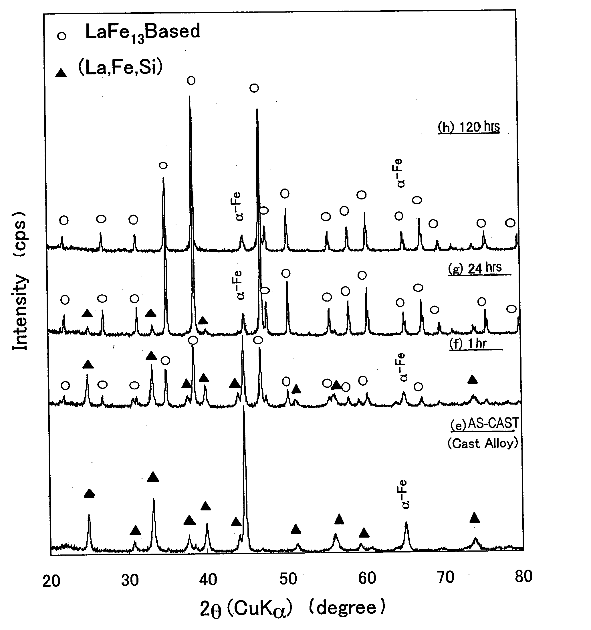
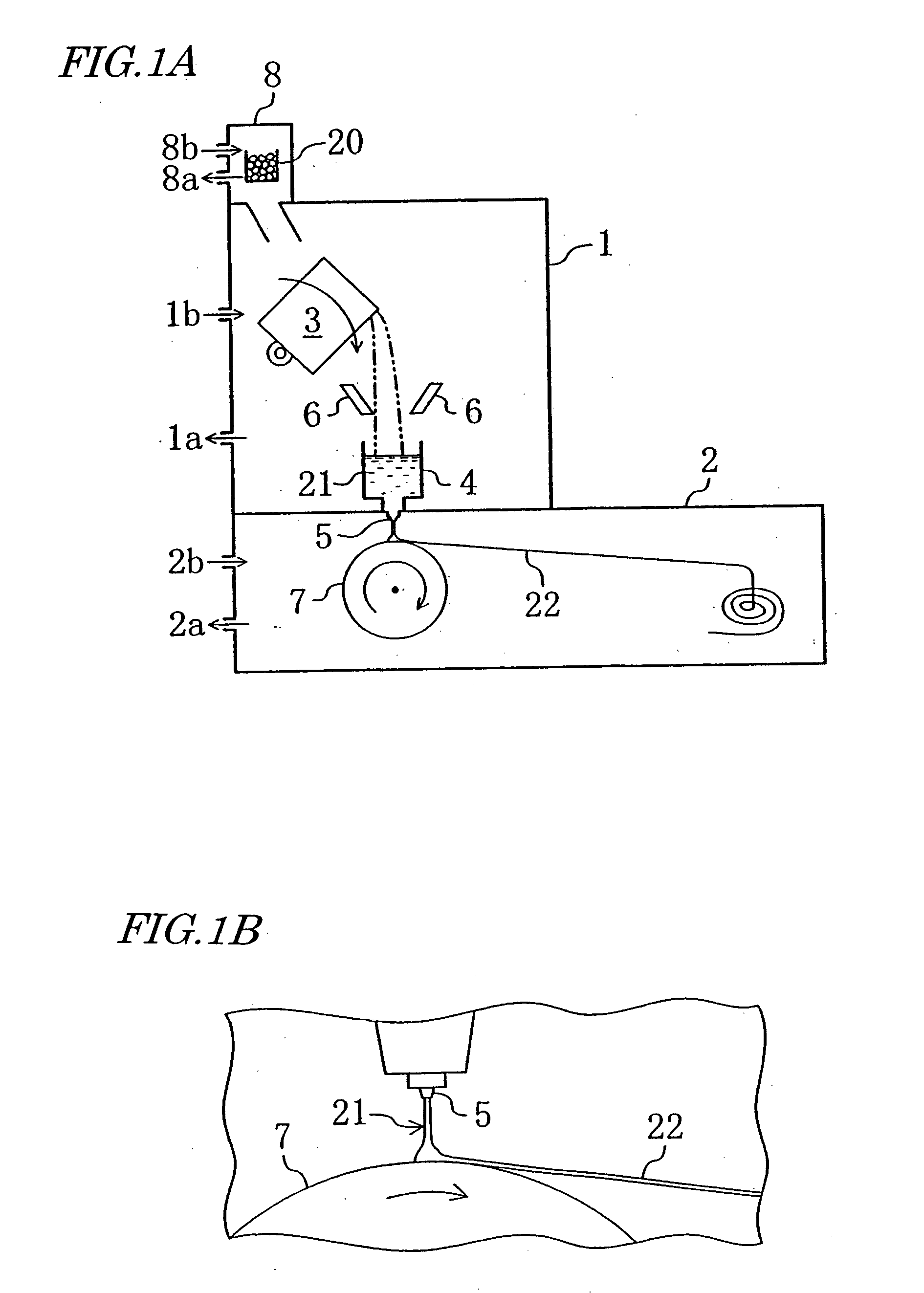
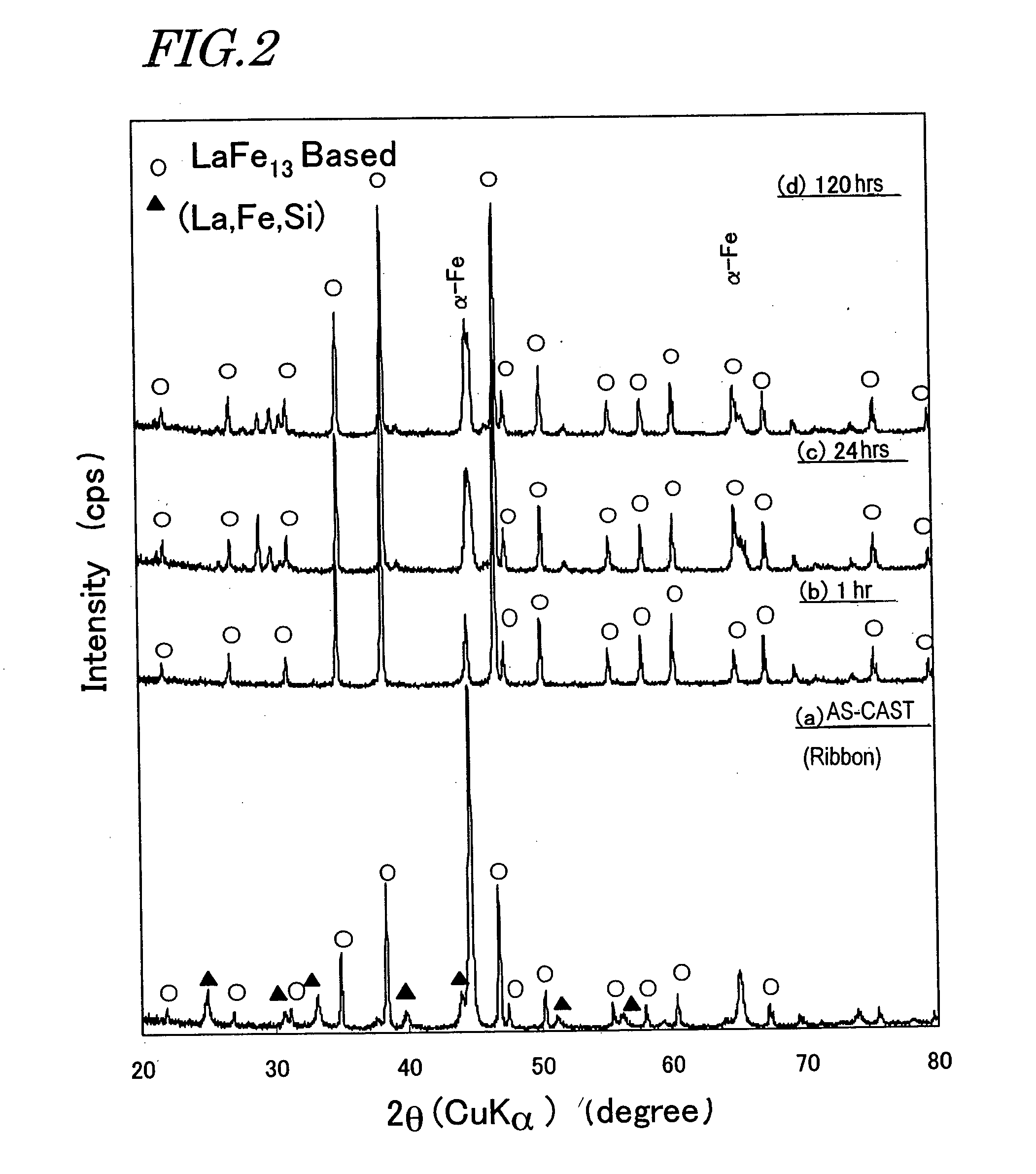
[0091] As in Experimental Example No. 1 described above, respective materials La, Fe and Si in predetermined amounts were mixed together such that an LaFe.sub.13-type compound phase having a composition La(Fe.sub.0.88Si.sub.0.12).sub.13 could be obtained. Then, the mixture was melted in a high frequency melting crucible, thereby obtaining a cast alloy. Thereafter, a melt of about 10 g of the resultant ingot cast alloy was ejected through a quartz nozzle with a diameter of about 0.8 mm onto a Cu roller that was rotating at a velocity of about 20 m / s, thereby obtaining an alloy ribbon as Sample (i).

[0092] Subsequently, Sample (i) was thermally treated at about 1,050.degree. C. within an Ar atmosphere for approximately 1 minute, approximately 5 minutes, approximately 10 minutes, approximately 30 minutes and approximately 60 minutes. The alloy ribbons obtained in this manner will be referred to herein as "Samples (j), (k), (l), (m) and (n...


PUM

PropertyMeasurementUnit
Temperatureaaaaaaaaaa

Abstract

A method of making a magnetic alloy material includes the steps of: preparing a melt of an alloy material having a predetermined composition; rapidly cooling and solidifying the melt to obtain a rapidly solidified alloy represented by: Fe100-a-b-cREaAbTMc where RE is at least one rare-earth element selected from La, Ce, Pr, Nd, Pm, Sm, Eu, Gd, Tb, Dy, Ho, Er and Tm and including at least about 90 at % of La; A is at least one element selected from Al, Si, Ga, Ge and Sn; TM is at least one transition metal element selected from Sc, Ti, V, Cr, Mn, Co, Ni, Cu and Zn; and 5 at %<=a<=10 at %, 4.7 at %<=b<=18 at % and 0 at %<=c<=9 at %; and producing a compound phase having an NaZn13-type crystal structure in at least about 70 vol % of the rapidly solidified alloy.

Description

[0001] 1. Field of the Invention[0002] The present invention relates to a magnetic alloy material that can be used effectively as a magnetic refrigerant material or a magnetostrictive material and also relates to a method of making such a magnetic alloy material.[0003] 2. Description of the Related Art[0004] A magnetic alloy, having a composition represented by the general formula: La.sub.1-zRE.sub.z(Fe.sub.1-xA.sub.x-yTM.sub.y).sub.13 (where A is at least one element that is selected from the group consisting of Al, Si, Ga, Ge and Sn; TM is at least one of the transition metal elements; RE is at least one of the rare-earth elements except La; and the mole fractions x, y and z satisfy 0.05.ltoreq.x.ltoreq.0.2, 0.ltoreq.y.ltoreq.0.1 and 0.ltoreq.z.ltoreq.0.1, respectively, and which will be referred to herein as an "LaFe.sub.13-based magnetic alloy") has an NaZn.sub.13-type crystal structure and exhibits giant magnetocaloric effect and magnetovolume effect at temperatures around its ...

Claims


Application Information

Patent Timeline
IPC IPC(8): H01F1/01H01F1/057H01F1/058
CPCH01F1/0571H01F1/015
Inventor KOGURE, RYOSUKEKANEKIYO, HIROKAZUNISHIUCHI, TAKESHIHIROSAWA, SATOSHI
Owner SUMITOMO SPECIAL METAL CO LTD
Why Eureka
Try Eureka